Decanting centrifuge with vibration isolation

a centrifuge and vibration isolation technology, applied in the direction of centrifuges, etc., can solve the problems of requiring a more complex structure to control the vertical position of the rotating plate, the movable ring and its driving elements are easy to be easily obtained, and the differential in blood amount is significant, so as to achieve the effect of simple structure, easy control, and easy acquisition

Inactive Publication Date: 2010-04-20
GLOBUS MEDICAL INC
View PDF42 Cites 14 Cited by
  • Summary
  • Abstract
  • Description
  • Claims
  • Application Information

AI Technical Summary

Benefits of technology

[0009]In accordance with one feature of the invention, a centrifuge provides vibration-isolating elements that resist the forces arising from imbalance in a centrifuge rotor. The vibration-isolating elements are placed with respect to the rotor such that the force-absorbing parts of the elements align directly with the forces created by the imbalanced rotor. Because there is no distance separating the imbalance forces from the counteracting forces, no torque is generated, as is the case in the prior art. This eliminates the necessity of counteracting the torque also and simplifies the construction.
[0011]In accordance with another feature of the invention, a movable decant ring is positioned to move vertically between one position wherein it does not engage the processing unit and the processing unit is free to swing during centrifugation and a second position where the ring engages the processing unit to hold it an a position that allows a supernatant in one chamber to flow to a second chamber. The decant ring is movable vertically but does not move circumferentially, in the direction of rotation of the rotor. This simplifies the structure of the movable ring and its driving elements. In the preferred embodiment, the ring is moved upward, into a position of engagement with the processing unit, by three electric solenoids. The advantage of electric solenoids is that they are easily obtained and easily controlled. It will be appreciate, however, that other driving elements may be used and that there may be more or fewer elements.

Problems solved by technology

The Wells patent does not describe structure for limiting vibrations of the centrifuge arising from imbalances in the rotor, and the Wells centrifuge is, accordingly susceptible to such vibrations.
Such a differential in the amount of blood is significant, and forces caused by this imbalance arise during centrifugation.
This prevents wear of the support frame or the plate that would result from such relative motions but, at the same time, requires more complex structure to control the vertical positions of the rotating plate.

Method used


Image

  • Decanting centrifuge with vibration isolation
  • Decanting centrifuge with vibration isolation
  • Decanting centrifuge with vibration isolation

Examples


Embodiment Construction

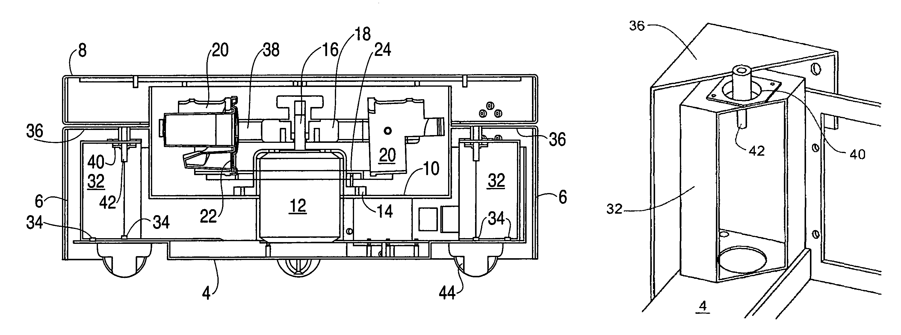
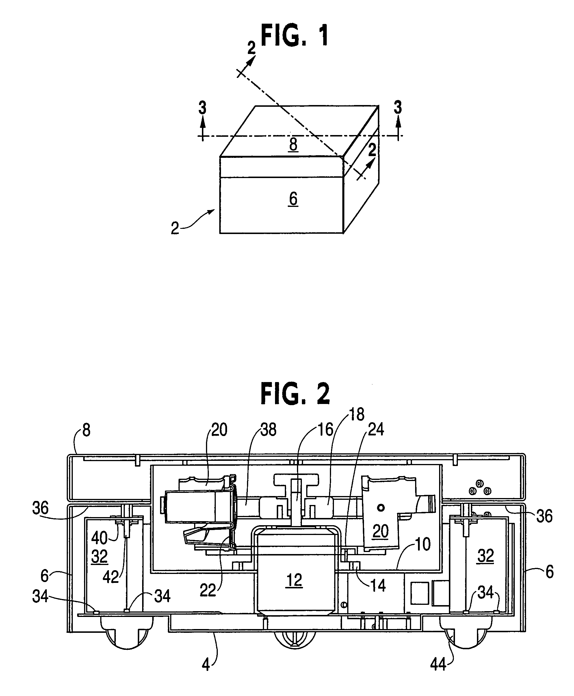
[0017]With reference to FIG. 1, a centrifuge 2 includes a base element 4 (see FIGS. 2 and 3) and an enclosure 6. The centrifuge can be any of various shapes and is generally designed to rest on a horizontal support surface, such as the floor, a table in a doctor's office or a surgical suite or on a dolly that is easily moved from one location to another. An enclosure 6 is supported on the base 4 in a manner to be described below and is configured to enclose the movable parts and particularly to provide a cavity for a centrifuge rotor and fluid processing units as will be described below. A lid 8 is provided to cooperate with the enclosure to cover the cavity when the centrifuge is in use so that the spinning rotor is protected. The lid 8 in preferably attached to the enclosure by hinges that allow the lid to be raised and the cavity exposed. As well, the lid may include safety elements that prevent raising or removing the lid during operation of the system, which would expose a movi...


PUM


Abstract

A centrifuge has a rotor for receiving a disposable processing unit. The centrifuge is configured such that the motor is attached to an enclosure and the enclosure is supported on a base. The connection between the base and the enclosure is a vibration isolator, and the isolator is positioned such that its effective line of action aligns with the effective plane of rotation of the rotor. In accordance with another feature of the invention, the processing units are held in a decanting position by a decant ring that moves vertically but does not rotate. The ring engages the top of the processing unit during decant and the abrasion is minimal.

Description

CROSS REFERENCE TO RELATED APPLICATIONS[0001]This is a continuation of U.S. patent application Ser. No. 10 / 629,825 filed Jul. 30, 2003 (now abandoned), which claims the benefit under 35 U.S.C. §119(e) of U.S. Provisional Application No. 60 / 400,072 filed on Aug. 2, 2002.TECHNICAL FIELD[0002]This invention relates to the art of centrifuges. In particular this invention relates to the art of decanting centrifuges with disposable liquid containers and to centrifuges with vibration isolation.BACKGROUND[0003]U.S. Pat. No. 5,707,331 (Wells) discloses a decanting centrifuge for separating through centrifugation two or more components of blood. The Wells patent teaches the use of a removable, disposable processing unit that has two fluid chambers. The processing unit is received in a centrifuge apparatus that can hold the processing unit selectively in particular orientations whereby supernatant fluids can be transferred from one chamber to another by way of gravity draining or centrifugal t...

Claims


Application Information

Patent Timeline
Patent Type & Authority Patents(United States)
IPC IPC(8): B04B5/02B04B9/14B04B5/04B04B9/12B04B11/06
CPCB04B5/0421B04B9/14B04B9/12
Inventor ELLSWORTH, JAMES R.MCGOVERN, PAUL
Owner GLOBUS MEDICAL INC
Why Eureka
Try Eureka