Insertion system and methods for nasogastric tubes
a nasogastric tube and insertion system technology, applied in the field of nasogastric tubes, can solve the problems of difficult safe insertion of nasogastric tubes, inability to precisely control the position of the end of the tube,
- Summary
- Abstract
- Description
- Claims
- Application Information
AI Technical Summary
Benefits of technology
Problems solved by technology
Method used
Image
Examples
embodiment 270
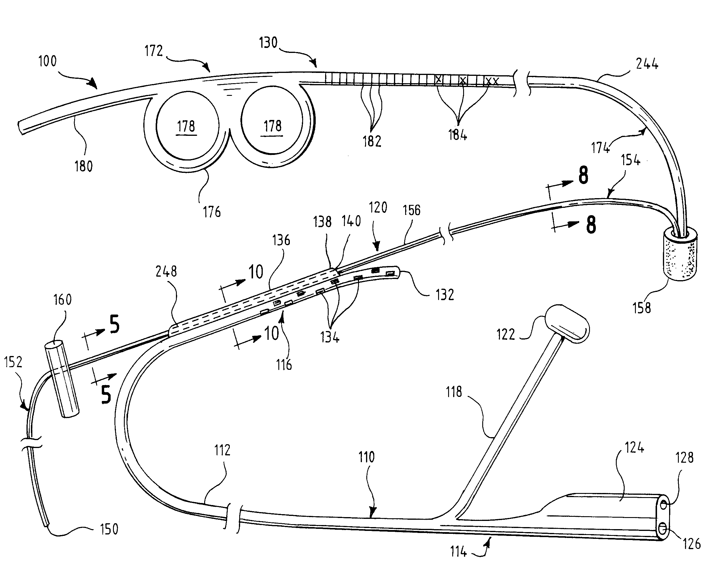
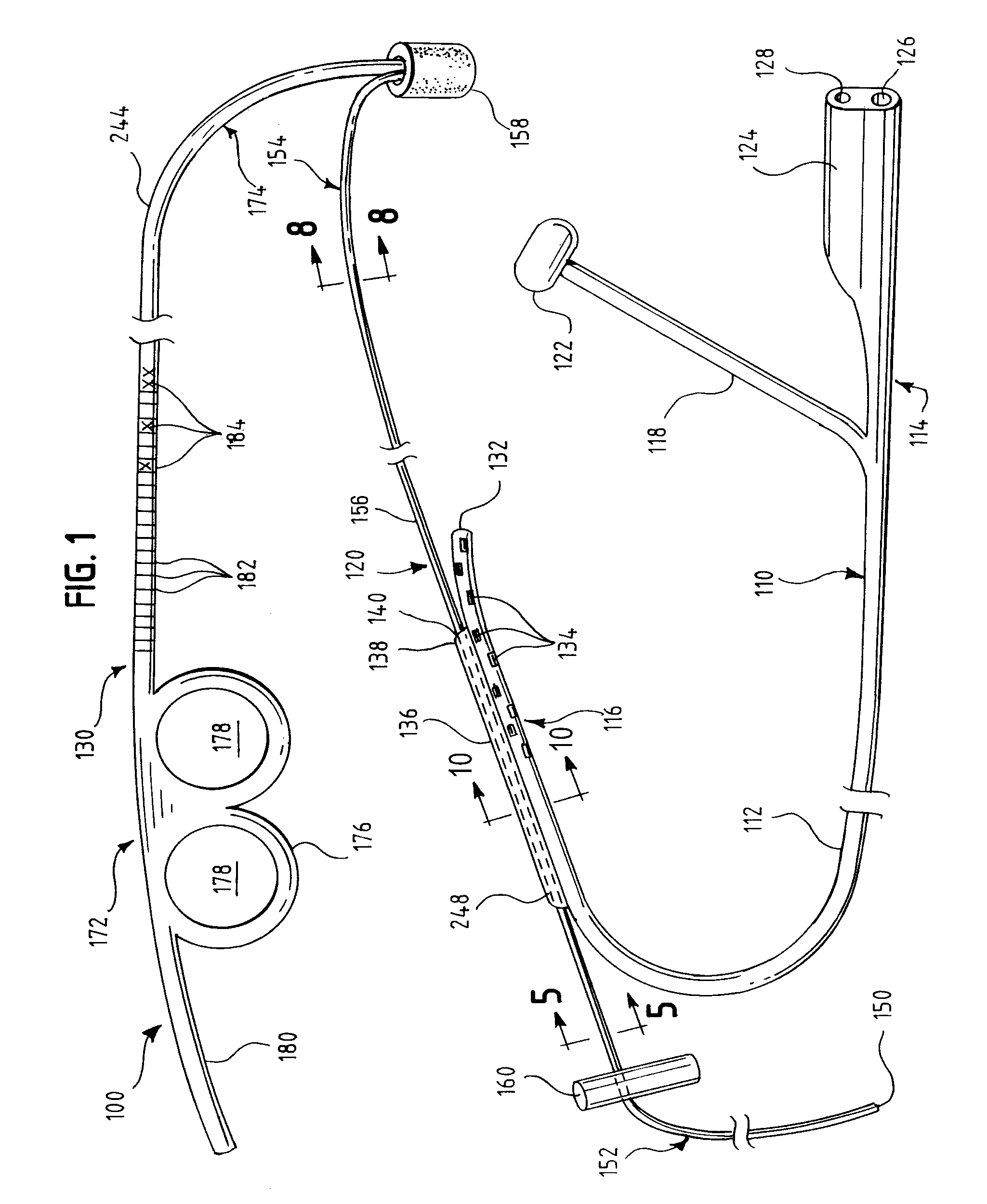
[0099]As best seen in FIG. 13, the insertion section 174 preferably has walls 196 forming a groove or channel 194 along at least a portion of its dorsal surface 244 to receive the guide element 120. An alternative embodiment 270 of the insertion section is shown in FIGS. 21-23 and described further in greater detail. Once the swallowable weight 158 of the guide element 120 is placed on the end of the inserter element 130, in order to retain the swallowable weight 158 in position, the user must apply light tension on the guide element 120. The channel 194 is adapted to retain the guide element 120 along the top surface of the inserter element 130 while tension is applied. This avoids undesirably deforming the insertion section 174 and prevents the guide element 120 from taking on a “bow string” configuration, which would interfere with the insertion process.
[0100]Although channel 194 is depicted in FIG. 13 as a generally U-shaped channel of considerable depth, other configurations co...
first embodiment
[0102]In FIG. 12, there is shown a first embodiment in which the tip 186 has an angular chamfered section 190 adapted to engage a mating receptacle 168 of the swallowable weight 158 of the guide element 120. Substantially vertical step walls mark the boundary between the full-thickness portion of the insertion section 174 and the stepped engagement section 188. The stepped engagement section 188 extends a short distance from the step walls 198 to the tip 186. The leading section 154 of guide element 120 is retained in channel 194 (FIG. 13) when the swallowable weight 158 is placed on tip 186 and light tension is applied to guide element 120.
second embodiment
[0103]In FIG. 13, there is shown a second embodiment in which the tip 186 has a substantially vertical wall section 192 instead of the angular chamfered section 190 of FIG. 12. Angular step walls 242 mark the boundary between the full-thickness portion of the insertion section 174 and the stepped engagement section 188. The stepped engagement section 188 extends a short distance from the step walls 242 to the tip 186. The leading section 154 (FIG. 12) of guide element 120 is retained in channel 194 when light tension is applied to guide element 120.
PUM
 Abstract
Description
Claims
Application Information
 - R&D
- Intellectual Property
- Life Sciences
- Materials
- Tech Scout
- Unparalleled Data Quality
- Higher Quality Content
- 60% Fewer Hallucinations
Browse by: Latest US Patents, China's latest patents, Technical Efficacy Thesaurus, Application Domain, Technology Topic, Popular Technical Reports.
© 2025 PatSnap. All rights reserved.Legal|Privacy policy|Modern Slavery Act Transparency Statement|Sitemap|About US| Contact US: help@patsnap.com


