Systems and methods for determining the state of a programmable fuse in an IC

a programmable fuse and ic technology, applied in the direction of resistance/reactance/impedence, instruments, semiconductor/solid-state device details, etc., can solve the problem that the use of this type of fuse is the minimum size of such fuses, and the laser may not be able to accurately cut the fuses

Inactive Publication Date: 2010-04-20
KK TOSHIBA
View PDF6 Cites 14 Cited by
  • Summary
  • Abstract
  • Description
  • Claims
  • Application Information

AI Technical Summary

Problems solved by technology

The opportunities to program laser fuses are limited to a small window of time in the manufacturing process when the fuses are exposed.
An additional limitation on the use of this type of fuse is the minimum size of such fuses.
This is a limitation because of the wavelength of the laser.
The wavelength of the laser is typically large relative to the feature size of contemporary IC's, so the laser may not be able to accurately cut the fuses.
The use of a laser to cut the fuses may also cause unintended collateral damage.
However, when the current is too large or applied for too long, the fuse can be damaged or even destroyed.
Other problems may arise.
For example, in some cases, a short circuit can occur in nearby components.
If the fuse is programmed with current that is too high, the fuse can be damaged or even destroyed, leaving it with an impedance well outside the desired range(s).
There is also the potential for collateral damage to other components in the device.
A conventional read circuit can distinguish between an unprogrammed (uncut) and programmed (cut) fuse, but cannot identify an improperly programmed (destroyed) fuse.

Method used


Image

  • Systems and methods for determining the state of a programmable fuse in an IC
  • Systems and methods for determining the state of a programmable fuse in an IC
  • Systems and methods for determining the state of a programmable fuse in an IC

Examples


Embodiment Construction

[0028]One or more embodiments of the invention are described below. It should be noted that these and any other embodiments described below are exemplary and are intended to be illustrative of the invention rather than limiting.

[0029]Broadly speaking, the invention includes systems and methods for detecting the state of a fuse or set of fuses in a device such as an integrated circuit. The fuse can be in any one of a set of states which can be determined by passing a current through the fuse, measuring the corresponding voltage (or voltage drop) and then comparing the voltage to a set of reference values.

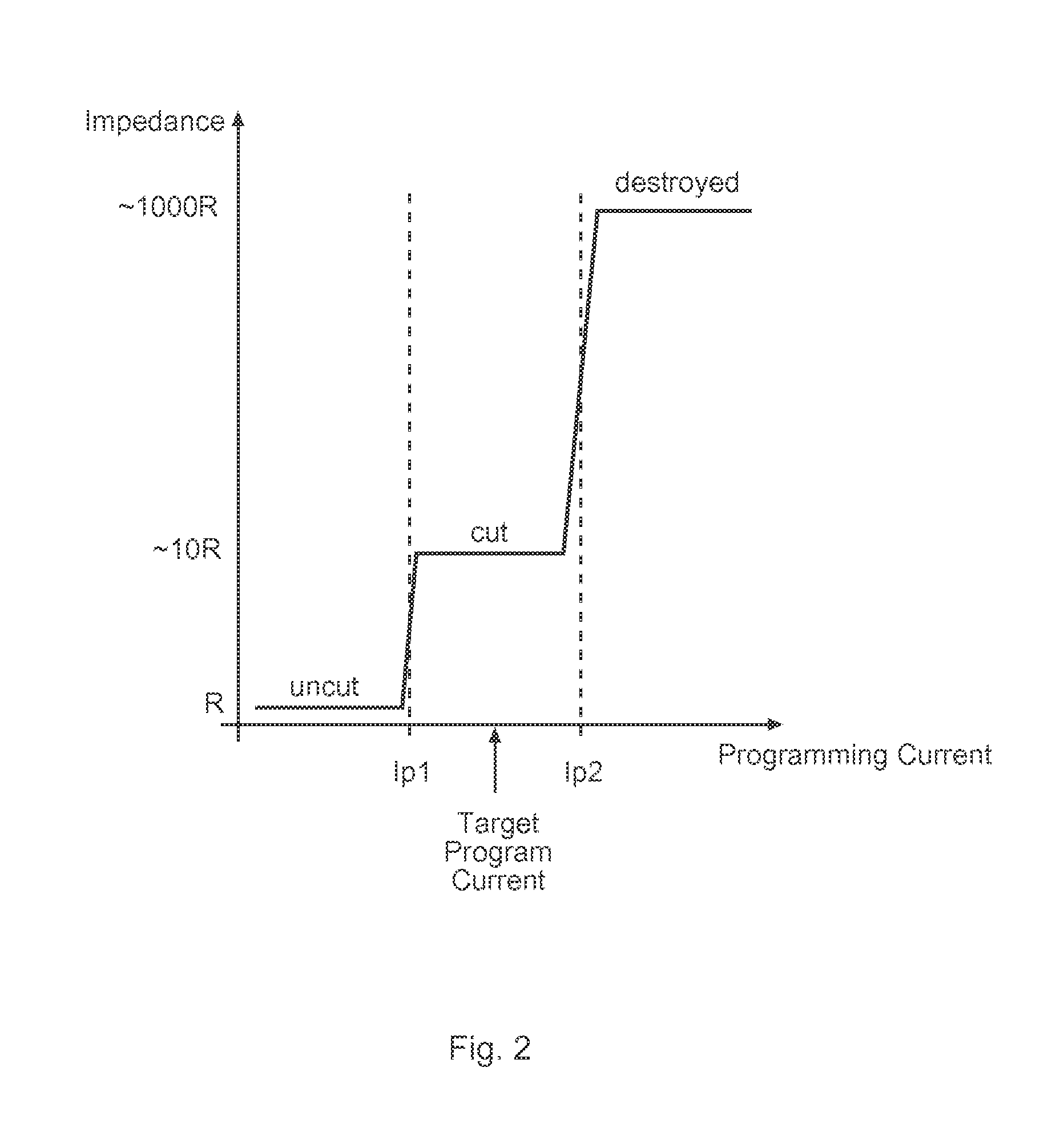
[0030]Before describing the invention in detail, it is helpful to understand how a fuse is programmed. This generally entails directing a large current through a fuse in such a way as to drive up the impedance. Typically, this increase is achieved through damage to the fuse itself. In a simple fuse, a conductive (metal) link is melted or evaporated by an excessive current, making the...


PUM


Abstract

Systems and methods for detecting the mode (a.k.a., state) of a fuse or set of fuses in a device such as an integrated circuit. One embodiment comprises a method for determining three fuse states (uncut, cut, and destroyed) by comparing the fuse voltage with two reference voltages. Each fuse state has a different (indicative) impedance and is associated with a fuse voltage. The fuse voltage is below, between, or above two reference voltages, thereby determining the fuse state. One embodiment includes the fuse in series with a read transistor as well as two reference voltage generators, each comprising a resistor and a transistor (equivalent to the read transistor). Both resistors' impedances are greater than the uncut fuse impedance and one is less than the cut fuse impedance. Two comparators are used to bracket the fuse voltage, indicating that the fuse is uncut, cut, or destroyed.

Description

BACKGROUND[0001]1. Field of the Invention[0002]The invention relates generally to fuses in integrated circuits (IC's) and more particularly to systems and methods for detecting the state of a fuse or set of fuses that are used to persistently store data in an IC.[0003]2. Related Art[0004]It is sometimes necessary to maintain some device specific information for a device such as integrated circuit (IC). It is convenient if not necessary to store this information in the IC itself. In order to do this, some part of the circuitry must act as a persistent storage. One solution is to incorporate into the circuitry a set of fuses and encode the desired information by programming it into the fuses. There are various trade-offs in the choice of components for this task, such as size, ease of programming, persistence etc.[0005]One conventional method is to incorporate laser fuses into a device. These fuses are programmed by evaporating the fuses' metal links (in other words, the fuses are “cu...

Claims


Application Information

Patent Timeline
Patent Type & Authority Patents(United States)
IPC IPC(8): G01R31/02G01R31/74
CPCG01R31/07G11C17/18H01L23/5256H01L2924/0002H01L2924/00G01R31/74
Inventor KANEKO, MASAAKI
Owner KK TOSHIBA
Why Eureka
Try Eureka