
Wearing parts system for detachable fitting of wearing parts for the tool of a cultivating machine

a technology of wearing parts and cultivating machines, applied in soil shifting machines/dredgers, constructions, etc., can solve the problems unfavorable leverage ratio, and uneven wear of tine parts and holder parts, so as to reduce the risk of unfavorable leverage ratio, reduce wear, and improve the effect of stability

Active Publication Date: 2010-04-27
COMBI WEAR PARTS AB
View PDF36 Cites 34 Cited by
  • Summary
  • Abstract
  • Description
  • Claims
  • Application Information

AI Technical Summary

Benefits of technology

[0053]The aforementioned tendencies of the tine to slide down from the holder nose are combated effectively by imitation of the so-called drawer effect, i.e. the particular contact faces between the holder part and the tine part will jam and thereby “hold together” the parts one in relation to the other.
[0054]One embodiment having a greater angle of inclination to the Y-line of symmetry of the inner, longitudinal peripheral line Pi along the locking device opening of the two symmetrical rear, essentially horizontal contact zones offers a further advantage. This greater angle makes it possible, through a displacement of the tine part up on to the holder part in the Y-direction, to absorb production tolerances with a minimized play between tine and holder, which yields good stability and thereby reduced wear. A poor fit and an unreliable locking device therefore increases the risk of tine fracture or lost tines.
[0055]The “drawer effect” as described above, the different inclination, conicity and rounding of the various contact faces in relation to the above-defined horizontal plane, side plane and vertical plane, and the special design of the locking device, means that a very exact guidance is obtained when fitting and removing the parts and that the ready-fitted tine is virtually free of play.
[0056]The locking device is not normally subjected to any actual compressive loads, but has essentially only a detaining function whilst the tine is lifted in the direction up from the surface which is being tilled.
[0058]The predetermined contact zone between the respective collars at the end faces of the collars, whilst the rest of the tine and holder collars are normally kept apart, substantially reduces the risk of occurrence of unfavourable leverage ratios.
[0060]According to the present invention, the desired advantages are achieved that the locking device can be introduced to about half its length before it comes round to the projecting plates or the larger cross-sectional sections, necessitating a hammer, that the locking device does not need to be held manually during the last driving down part of the introduction and that the fitting and removal of the locking device, especially where tines are placed relatively close together, is made substantially easier in the case of the vertically placed locking device than compared with, for example, the horizontally placed locking device for use with the abovementioned tine in U.S. Pat. No. 2,689,419.

Problems solved by technology

The component forces Fx, Fy and Fz can also, as a result of their leverage ratio, give rise to troublesome torque loads, which have to be absorbed via double contact zones disposed on either side of the axis about which the rotation occurs.
These projections and recesses respectively are herein meant to eliminate the mobility between the holder part and the tine part which is a consequence of inevitable production tolerances, but they will also absorb torque loads, which can lead to the emergence of undesirable leverage ratios after a certain period of asymmetrical wear.
Moreover, both the tine part and the holder part will suffer essentially equal wear, with the result that both of them have to be replaced once the wear has reached its maximum level.
This is very costly, of course, and since each holder part, moreover, is welded to the bucket, the down time is far longer than with a rapid replacement of just the wearing part.
A further and very serious problem with the abovementioned coupling systems is that the locking device risks being cut off by the shearing forces which are generated, on the one hand, when the tine part and the holder part are displaced horizontally toward each other owing to continuous wearing down of the angled stop faces and of the stop faces on the collars, and, on the other hand, when the coupling system is subjected to unfavourable rotational loads about an unforeseen contact, newly arisen because of the wear, between the collars of the wearing parts system.
As the wear increases on the original vertical stop faces designed for wear, a second and undesirable secondary contact zone will form, however, between the rear edge of the tine collar of the wearing part and the front edge of the collar of the holder, i.e. a secondary stop zone is formed around the tine collar and the holder collar in the vertical plane XZ of the respective collar, which edges / vertical planes do not initially meet and which secondary stop zone, moreover, will gradually grow.
A torque leverage which is very detrimental to the strength will in this case be obtained for the majority of load cases, which leverage will give rise to the shearing forces which will cut off the locking device.
In the coupling system according to U.S. Pat. No. 2,689,419, the locking wedge is at its weakest at the tapered end of the locking wedge, precisely where the said shearing forces are likely to be greatest, i.e. on the friction surfaces between the wearing part and the holder part, both owing to the leverage ratios of the said loads and owing to the fact that the play between the collars is equally great all the way round, with the result that the undesirable secondary contact zone will very easily be formed such that the leverage ratio is obtained which is most unfavourable to the construction.
Further, when an extensive wear has occurred on the contact and stop faces, the remaining material between the locking device openings in the hood and the rear edge of the wearing part, and the material between the horizontal friction surfaces of the holder beak and the locking device opening through the beak will have been weakened so much that cracks are formed, after which the coupling is broken apart.
This solution adds to the cost and complexity of production, at the same time as the increased material thickness of the beak also means a higher profile of the tine in the portion over the beak, which is unfortunate from the penetration aspect.
Moreover, the so-called exchange will be worse owing to the material which has necessarily been applied rearward to the wearing part of the known tine.
Because of the tapered shape of the holder beak in the direction of the front edge, previously known coupling systems have shown a tendency to allow the tine part to move forward when vertical load is applied to the tine point, i.e. to allow the tine part to slide off along the holder part performing a ski jump, thereby subjecting the locking device to undesirable stress.
These disadvantages are constituted, above all, by the risk that the locking device, when dynamic vertical load is applied to the tine point, will “work itself out” of the locking device opening such that the tine point falls off, and by the fact that the said dynamic vertical loads subject the locking mechanism to much more serious shearing forces in the case of vertical placement than in the case of a horizontal placement.
Known locking devices have normally to be removed by means of powerful hammer blows, which means that the more solid types quickly become unusable owing to the wear and the deformation which occurs on the lock body and along the locking device opening.
The wedge-shaped type, though simple to fit and remove, also has a greater tendency to come loose owing to the vibrations and dynamic stresses which are generated during normal operation.
In the case of elastic locking devices, the said pretensioning will accelerate the ageing of the elastic element and thereby reduce the maximum working life of the locking mechanism.
When the rubber or the spring ages, the pretensioning required for the locking device to remain seated in the opening despite the said problems with vibrations, unfavourable tolerance levels, wear and other stresses on the contact faces, etc., all of which adversely affect the horizontal motions of the wearing part on the holder part, will in fact steadily decrease until the locking device, quite simply, can fall out by itself.
However, elastic locking devices of this kind, introduced into an inner cavity, are difficult to remove, since the compression which is necessary for the removal of the locking device becomes more difficult to achieve.
The above-stated method of attempting to remove the locking device by hammer blows often results, if a spring is used, in the said spring being broken off.
If a body which is elastic in all directions is used, a rebound is instead obtained, which is caused by the elastic element not being able to expand in another direction upon impact, with the result that the compression and the expansion occur in substantially the same direction as the hammer blows.
Should “the dirt”, moreover, dry or freeze into a compact body, the replacement of tines is made yet more difficult.
These locking devices, too, are therefore very difficult to undo after a certain period of use.
Should the extra space along the hole be made sufficiently large or continuous to allow removal of the dirt from the outside, then the disadvantage is instead obtained that the strength of the tine naturally declines when the thickness of the material decreases, without an actual solution to the dirt-sticking problem.
The said sliding zone has, moreover, the worst leverage ratio of all hood-type wearing parts systems, i.e. the longest leverage from the Y-line of symmetry, with the result that the shearing forces caused by occurring torque loads are most intensive in this section.
Having the locking device carry out the securement in the holder part instead of against the hood roof leads to undesirable loads being transferred via the locking device to the holder part.
Further, a placement of the securing plate against the hood roof leads instead to the elastomer hollow coming so “high up” that the said unbroken cross section cannot be obtained.

Method used


Image

  • Wearing parts system for detachable fitting of wearing parts for the tool of a cultivating machine
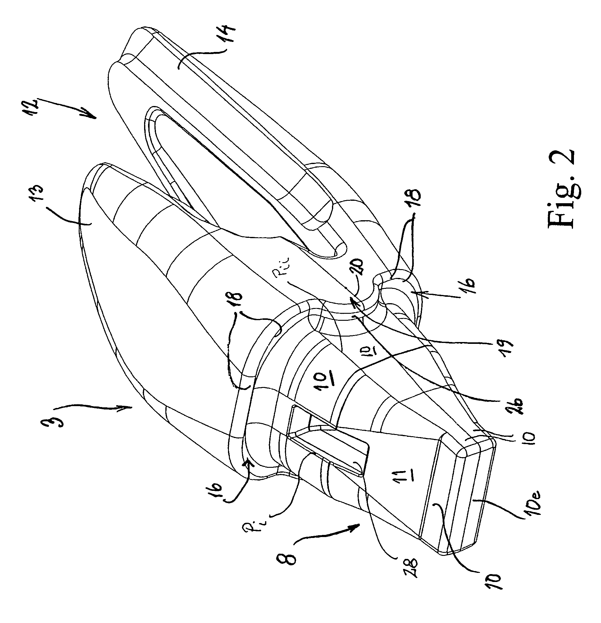
  • Wearing parts system for detachable fitting of wearing parts for the tool of a cultivating machine
  • Wearing parts system for detachable fitting of wearing parts for the tool of a cultivating machine

Examples


Embodiment Construction

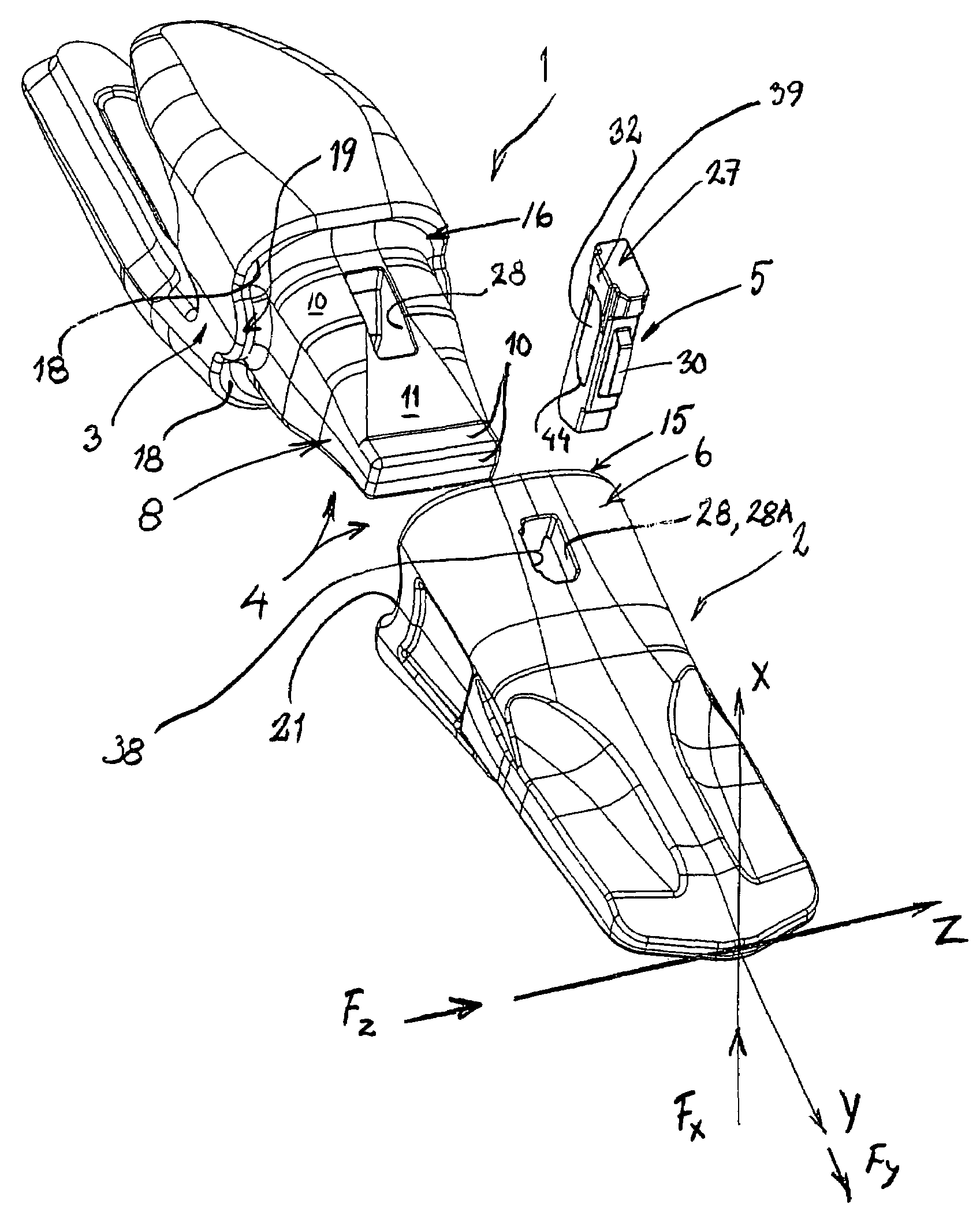
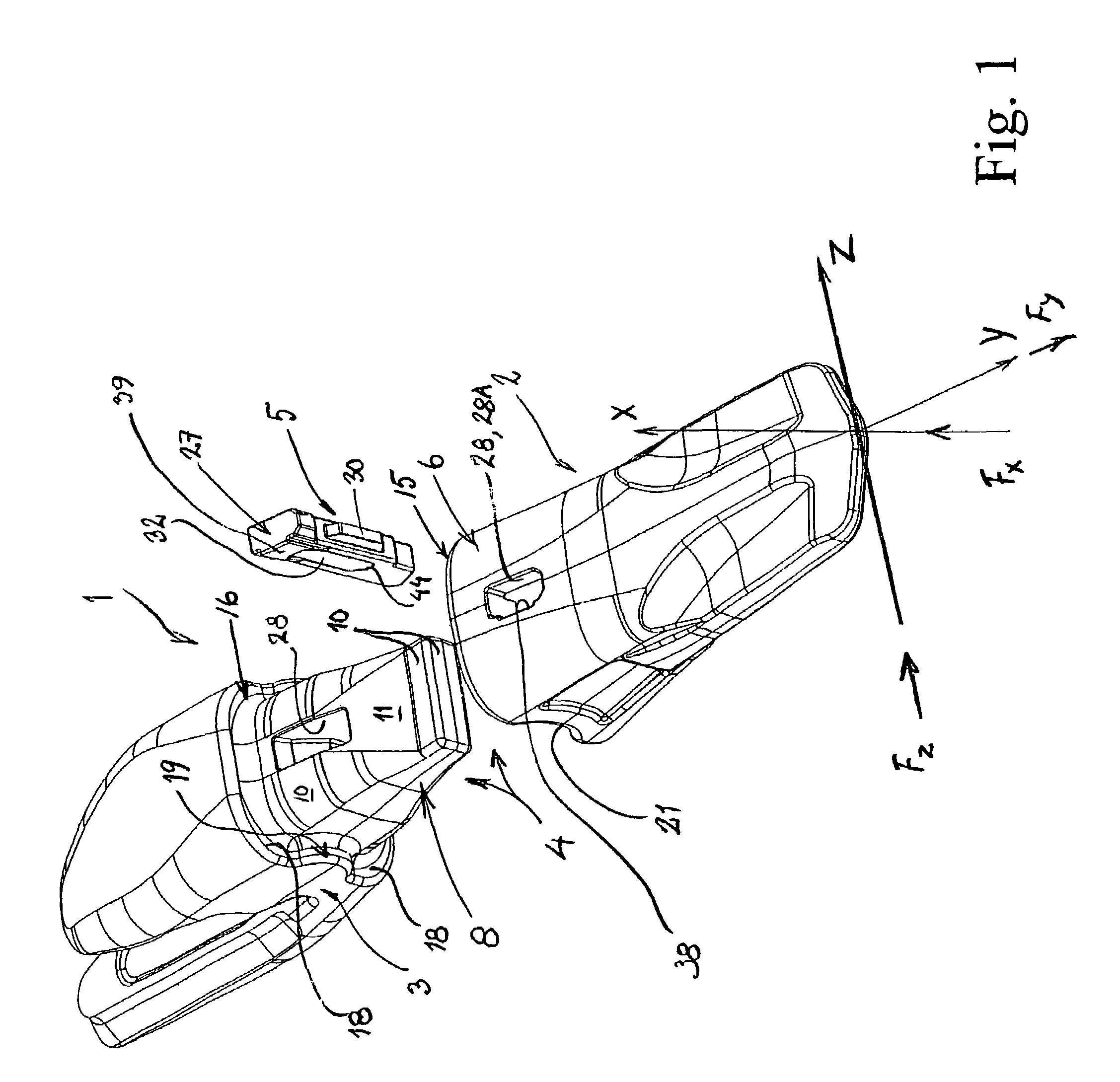
[0086]With reference to FIG. 1, parts of a wearing parts system 1 according to a preferred embodiment of the present invention are shown schematically, which wearing parts system 1 is intended for a detachable fitting of exchangeable wearing and / or replacement parts 2 to the tool of a cultivating machine, here, more particularly, tines on the bucket of a machine (not shown in detail).

[0087]The invention which is described in greater detail below relates primarily, of course, to parts which are intended to be consumed, i.e. become worn, but any exchangeable working parts which have different functions in connection with the use of the particular tool also lie within the inventive concept. Below, the invention will only be described in detail, however, for an embodiment which comprises tines.

[0088]The wearing parts system 1 is shown in FIG. 1 together with a system of coordinates comprising three coordinate axes X, Y, Z for illustrating the mutual positions and extent relative to one ...


PUM


Abstract

The invention relates to a wearing parts system (1) intended for the tool of a tilling machine of the type which comprises a holder part (3), having a front end part (8), and an exchangeable wearing and / or replacement part (2), arranged over this end part and comprising a hood-shaped (6) hollow (7) which, when the wearing part (2) is fitted in place, is designed to grip over the end part and is fixed thereto by means of at least one locking device (27) placed through interacting openings (28), the end part and the hollow having front, rear and collateral contact zones (9, 22, 23), each comprising contact faces (10, 25, 26), disposed one on the holder part and one on the wearing part, for the absorption of acting vertical, horizontal and collateral forces Fx, Fy and Fz. The contact faces (25, 26) are designed to interact so as, on the one hand, to limit the pushing-on of the wearing part over the holder part and, on the other hand, to ensure that the contact between the contact faces will be made, primarily, at the common centre M0, of the two radii (of a recess and a projection) essentially in the horizontal plane YZ and secondarily, as the wear has progressed, symmetrically about this mid contact point as an increasingly large contact zone (22′, 23′).

Description

TECHNICAL FIELD[0001]The present invention relates to a wearing parts system intended for the tool of a tilling machine of the type which comprises a holder part, fixedly attached to the tool and comprising an essentially wedge-shaped or beak-shaped front end part projecting in the working direction of the tool, and an exchangeable wearing and / or replacement part, detachably arranged over this holder beak and comprising a rear, essentially hood-shaped hollow, which is matched to the holder beak of the holder part and interacts therewith and which, when the wearing and / or replacement part is fitted in place, is designed to grip over the holder beak and is fixed thereto by means of a detachable locking mechanism comprising at least one locking device, placed through interacting openings made through the holder part and the wearing and / or replacement part, the holder beak and the hollow of the wearing and / or replacement part having, arranged in relation to an essentially cross-vertical...

Claims


Application Information

Patent Timeline
Patent Type & Authority Patents(United States)
IPC IPC(8): E02F9/28
CPCE02F9/2825E02F9/2858E02F9/2841E02F9/28
Inventor KARLSSON, MAGNUSMOLIN, NICLAS
Owner COMBI WEAR PARTS AB
Learn More