High-frequency circuit and communications apparatus comprising same

a communication apparatus and high-frequency circuit technology, applied in electrical devices, coupling devices, transmission, etc., can solve the problems of extremely difficult to keep the relation between output power and detection voltage constant, and difficulty in reducing the size of communications apparatus, so as to reduce differences, reduce second harmonics, and reduce the effect of attenuation

Inactive Publication Date: 2010-04-27
HITACHI METALS LTD
View PDF17 Cites 91 Cited by
  • Summary
  • Abstract
  • Description
  • Claims
  • Application Information

AI Technical Summary

Benefits of technology

[0013]The harmonics-suppressing circuit is preferably a lowpass filter circuit or a notch filter circuit constituted by one or more transmission lines and one or more capacitors, or an attenuator circuit constituted by one or more resistors. Although the harmonics-suppressing circuit has conventionally been disposed in a main line, through which a transmission signal and a receiving signal pass, it is disposed between the coupler and the detection diode in the present invention. This makes it possible to drastically reduce the loss of the main line, through which a transmission signal and a receiving signal pass, resulting in higher quality and lower power consumption of communications.
[0014]The lowpass filter circuit or the notch filter circuit constituting the harmonics-suppressing circuit in the high-frequency circuit of the present invention preferably has an attenuation pole adjusted to 2 or 3 times the passband frequency, without attenuation at the passband frequency. This makes it possible to reduce only harmonic signals while keeping the detection voltage constant.
[0015]The lowpass filter circuit and the notch filter circuit are effective when a signal being detected has a relatively narrow passband.
[0016]When used in a dual-band wireless communications apparatus selectively using first and second frequency bands, the attenuator circuit constituted by one or more resistors is more preferable than the lowpass filter circuit and the notch filter circuit, because the attenuator can attenuate a signal in a wide band. For instance, when the first and second frequency bands are a 2.4-GHz band and a 5-GHz band, respectively, detection in the 5-GHz band is insufficient in the lowpass filter circuit and the notch filter circuit, because a second-harmonic signal in the first frequency band is substantially 5 GHz. On the other hand, the attenuator circuit attenuates not only a detected signal from the coupler but also reflected waves of harmonic signals generated by the detection diode. Although the use of the attenuator circuit makes it necessary for the coupler to have a large coupling degree to keep the detection voltage constant, it is advantageous in providing sufficient attenuation in a broad band.
[0017]The harmonics-suppressing circuit is preferably a notch filter constituted by an inductor, a diode, a capacitor, a resistor and a power-supplying terminal for attenuating frequencies 2 or 3 times those of transmission signals in a first frequency band (for instance, 2.4-GHz band) and a second frequency band (for instance, 5-GHz band), and it is preferable to use a variable notch filter having a variable resonance frequency attenuated by voltage applied to the power-supplying terminal. By ON / OFF of the power-supplying terminal of the variable notch filter, the attenuation pole can be set to a frequency 2 times that of the first transmission signal when a transmission signal in the first frequency band is sent to the antenna, and to the frequency of a second harmonic of the second transmission signal when a transmission signal in the second frequency band is sent to the antenna. Thus, by changing the attenuation poles in both bands, the second harmonics can be reduced by one filter.
[0018]A matching circuit constituted by a shunt inductor connected to the coupling line of the coupler, and / or a matching circuit constituted by a shunt inductor and a phase circuit connected between the coupling line of the coupler and the detection diode are preferably disposed between the secondary line of the coupler and the harmonics-suppressing circuit. This matching circuit is preferably adjusted such that impedance matching is obtained between the coupling line of the coupler and the detection diode in a first frequency band (for instance, 2.4-GHz band). This increases the detection voltage in a 2.4-GHz band, in which the coupler has a small coupling degree and the detection voltage is small, thereby reducing differences from the detection voltage in a 5-GHz band. This matching circuit can separately adjust impedance matching in an amplitude direction by the shunt inductor and impedance matching in a phase direction by the phase circuit on a Smith chart. As a result, impedance matching can be easily adjusted between the coupling line of the coupler and the detection diode in a 2.4-GHz band.

Problems solved by technology

Accordingly, it needs many parts, resulting in difficulty in reducing the size of an communications apparatus.
However, because both transmission powers in a 2.4-GHz band and a 5-GHz band should be detected in the circuit shown in FIG. 16, it is extremely difficult to keep the relation between output power and detection voltage constant, when the coupling degree of the coupler largely depends on a frequency.

Method used


Image

  • High-frequency circuit and communications apparatus comprising same
  • High-frequency circuit and communications apparatus comprising same
  • High-frequency circuit and communications apparatus comprising same

Examples


Embodiment Construction

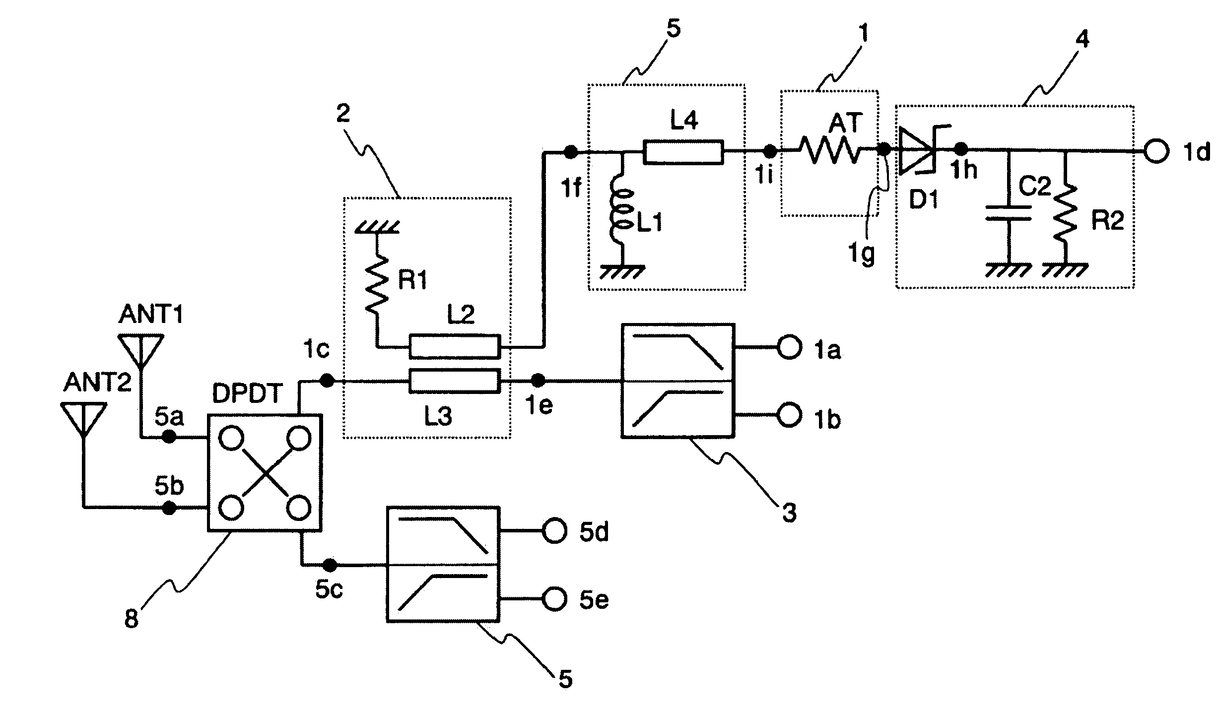
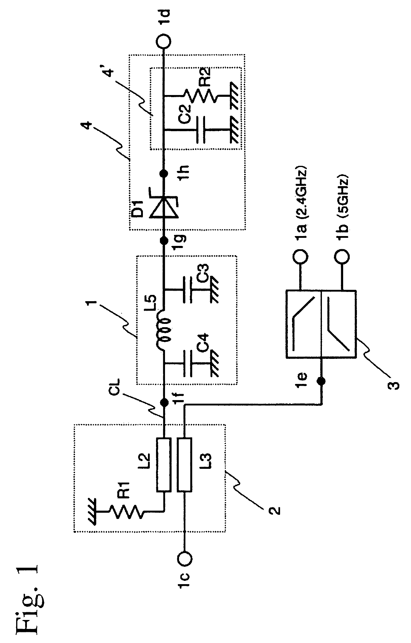
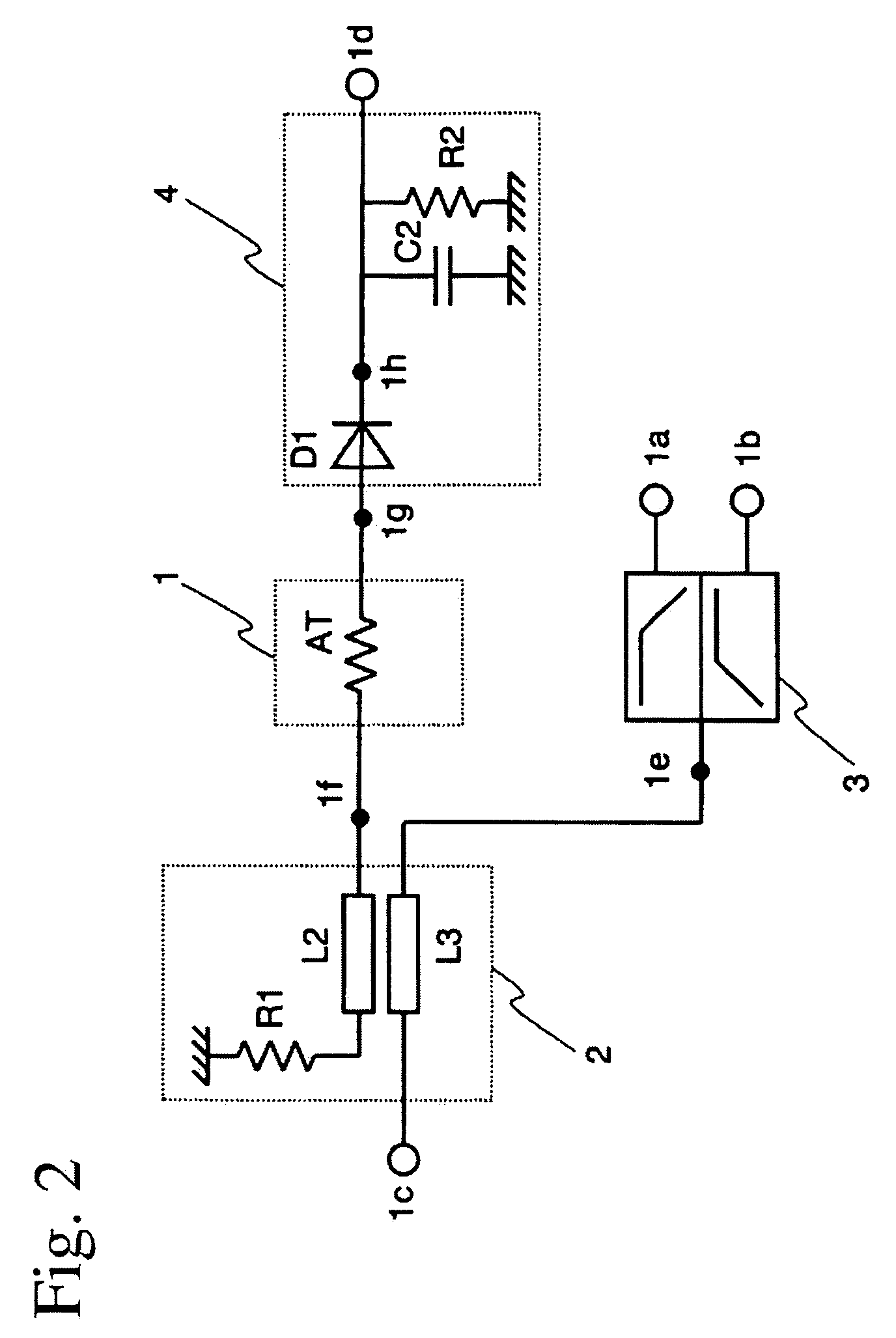
[0037]FIG. 1 shows a high-frequency circuit according to one embodiment of the present invention. This high-frequency circuit comprises a diplexer 3, a coupler 2, a detector 4 comprising a detection diode D1 and a smoothing circuit 4′, and a harmonics-suppressing circuit 1 disposed between the coupler 2 and the detection diode D1. The diplexer 3 is constituted by a combination of a lowpass filter and a highpass filter, which are constituted, for instance, by LC circuits. The coupler 2 is constituted by a primary line L3, a secondary line L2 and a resistor R1. A coupling line CL on the side of the secondary line L2 of the coupler 2 is connected to the harmonics-suppressing circuit 1 and the detector 4 in series. The detection diode D1 in the detector 4 has an anode terminal 1g connected to the harmonics-suppressing circuit 1, and a cathode terminal 1h connected to the smoothing circuit 4′.

[0038]A transmission signal in a 2.4-GHz band (IEEE802.11b) and a transmission signal in a 5-GHz...


PUM


Abstract

A high-frequency circuit for use in a dual-band wireless communications apparatus selectively using first and second frequency bands, comprising a diplexer connected to the output of a power amplifier for sending either one of transmission signals in the first and second frequency bands to an antenna, a coupler having a primary line connected to a common end of the diplexer and a secondary line, a detector comprising a detection diode for detecting a transmission power of a high-frequency signal sent from the secondary line of the coupler, and a harmonics-suppressing circuit disposed between the secondary line of the coupler and the detection diode.

Description

FIELD OF THE INVENTION[0001]The present invention relates to a high-frequency circuit handling at least two communications systems and having a function to detect a transmission power, and an apparatus comprising such high-frequency circuit for wireless communications among electronic appliances.BACKGROUND OF THE INVENTION[0002]Data communications by wireless LAN (local area network) according to IEEE802.11 are now widely used. They are used as signal-transmitting means in place of personal computers (PCs); PC peripherals such as printers, hard disk drives, broadband routers, etc.; electronic appliances such as facsimiles, refrigerators, standard-definition televisions (SDTVs), high-definition televisions (HDTVs), digital cameras, digital video recorders, cell phones, etc.; and wired communications of automobiles and aircrafts, and wireless data transmission is conducted among these electronic appliances.[0003]There are IEEE802.11a, IEEE802.11b and IEEE802.11g as the standards of wi...

Claims


Application Information

Patent Timeline
Patent Type & Authority Patents(United States)
IPC IPC(8): H01P5/18
CPCG01R21/10
Inventor FUKAMACHI, KEISUKEKEMMOCHI, SHIGERU
Owner HITACHI METALS LTD
Why Eureka
Try Eureka