
Data communication network using optical power averaged multiplexing

a data communication network and optical power technology, applied in the field of optical communication systems, can solve the problems of large power required to achieve the required conversion/transformation, unsatisfactory complications, and size problems, and achieve the effects of improving speed, size, power consumption and flexibility

Inactive Publication Date: 2010-04-27
LOCKHEED MARTIN CORP
View PDF20 Cites 0 Cited by
  • Summary
  • Abstract
  • Description
  • Claims
  • Application Information

AI Technical Summary

Benefits of technology

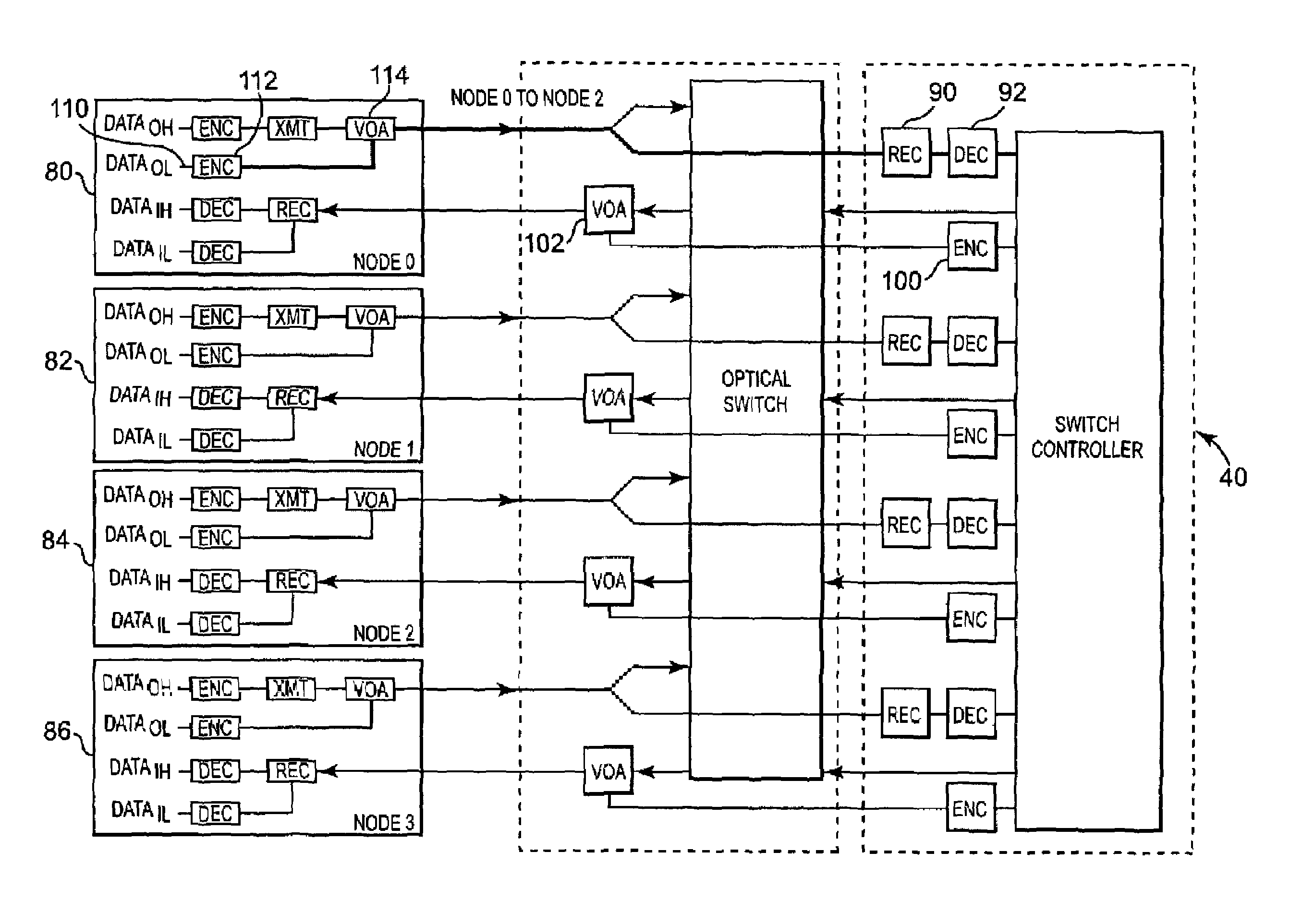
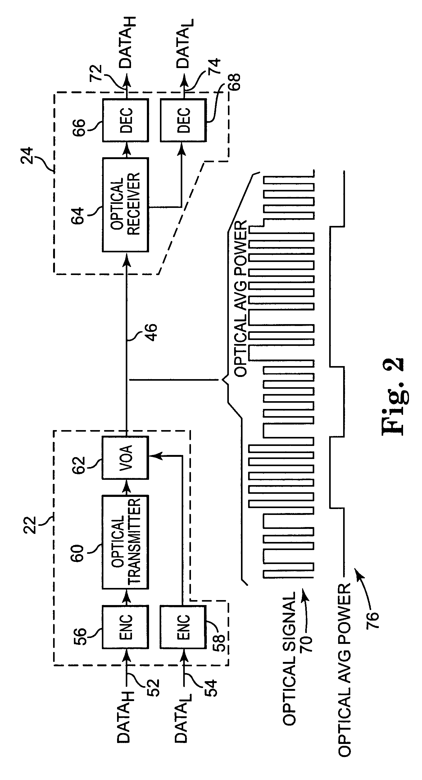
The present invention provides a communication protocol and system that allows for fast and efficient communication of information between multi-processing systems. The system is designed to use all optical components, minimizing complications related to optical-electrical-optical transformations. The communication tasks are distributed between various components and do not rely upon the switching network to achieve every function. The protocol utilizes two separate but very related cycles to achieve its functionality. The system is made up of nodes, a switch, and a controller, each with buffering capabilities to allow appropriate coordination with all other components of the network. The switching network is configured to allow the transmission of data in an all optical format and is independent of the data format being received and / or transmitted. The controller provides the arbitration and security functions for the network. The arbitration cycle is achieved utilizing optical power averaged multiplexing, and all arbitration and switching functions are independent of the optical switch. The technical effects of the invention include faster and more efficient communication, reduced size and power consumption, and flexibility.

Problems solved by technology

Present optical communication networks use both electrical and optical components to achieve switching and routing, which can provide undesirable complications.
First, considerable power is required to achieve the required conversion / transformations.
Further, the above-mentioned conversions also create size issues.
Along with the requirement for additional components, cost and reliability issues are also raised.
That is, the increased number of components obviously requires more cost and the greater possibility of failure.
Further, the operation constraints of the optical / electrical conversions also create limits on the operating capabilities of the system.
Specifically, the components must be configured to accommodate conversions at various rates, thus placing additional operational constraints on the system itself.
These limitations also complicate the scalability of the system, as changes to the data rates and / or protocols would require similar changes to all the components.
While optical switching is attained, the addressing / arbitration is not necessarily performed independent of the payload.
As such, several limitations continue to exist.
This solution, however, requires the separation of the header and payload, and considerable buffering to insure operation.

Method used


Image

  • Data communication network using optical power averaged multiplexing
  • Data communication network using optical power averaged multiplexing
  • Data communication network using optical power averaged multiplexing

Examples


Embodiment Construction

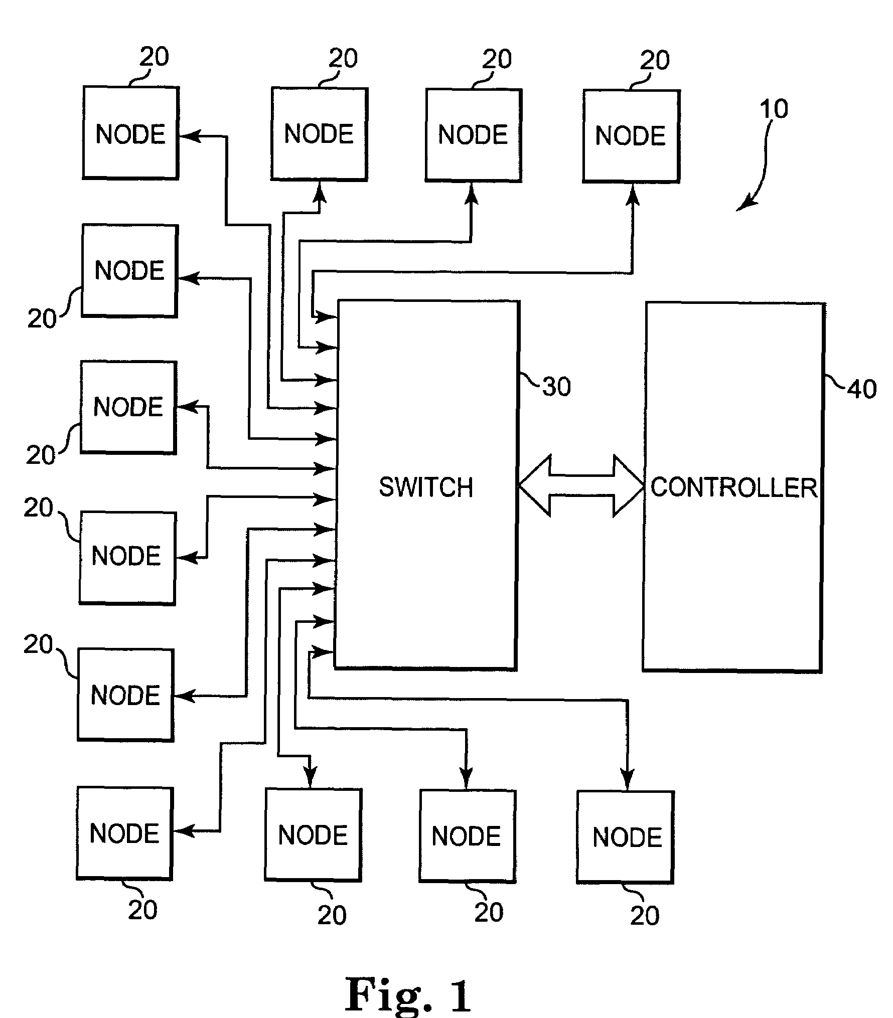
[0023]As can been seen in FIG. 1, one embodiment of the present invention includes a data communication system 10 which includes a plurality of nodes 20, each of which are connected to an optical switch 30. Additionally, the communication system 10 also includes a controller 40 which is connected to switch 30. It is understood that all of the above connections or attachments, as shown in FIG. 1, indicate a transmission path between these various components. While FIG. 1 illustrates one potential layout, the system is not restricted to the specific physical configuration shown.

[0024]As will be further outlined below, each node 20 is configured to transmit and receive data. Nodes 20 may take on many different forms, including a part of separate processing systems, and / or remote components of different types. For example, some of the nodes could be memory resources accessed by other nodes that are processors. In general, the nodes could be either a homogenous or heterogeneous collectio...


PUM


Abstract

An optical network system, including multiple nodes, an optical switch, and a switch controller, is configured to achieve communication in the optical domain. Each node is configured to receive both high frequency and low frequency inputs, generally utilized for handling data and addressing information, respectively. The two types of information are combined to create an amplitude modulated optical signal. Subsequently, the two types of information are separated by examining the optical power average of the signal being transmitted. Using one portion of the signal for addressing information, the switch controller can perform necessary routing and arbitration functions. Appropriate communications can then be sent back to the nodes and the optical switch to achieve the necessary configuration. The protocol utilized allows for subsequent arbitration and data transmission cycles, allowing the system and switch controller to configure transmission paths and arbitrate any communication issues. All optical data transmission is then commenced.

Description

BACKGROUND OF THE INVENTION[0001]The present invention relates to optical communication systems. More specifically, the present invention relates to optical networks used for communication between multi-processing systems.[0002]Switching networks are widely used to provide very flexible network communication. Presently used communication methods, known as packet routing, allows for the effective transmission of information over a network from one component to a targeted destination. In these systems, the information is first configured as a packet which typically includes addressing information and data. The addressing information is typically contained in a header, which is then followed by the data (often referred to as the payload). Using this format, switching networks are capable of determining a desired address, and subsequently transmitting the packet from a source to a defined destination.[0003]As is well known, optical communication is widely used in today's society for num...

Claims


Application Information

Patent Timeline
Patent Type & Authority Patents(United States)
IPC IPC(8): H04J14/00
CPCH04J14/00
Inventor STEVENS, RICK C.WHALEY, GREGORY J.LEININGER, BRIAN S.
Owner LOCKHEED MARTIN CORP
Learn More