Supercharge Your Innovation With Domain-Expert AI Agents!

Current supply for luminescent diodes

a technology of leds and current supply, applied in the direction of lighting and heating apparatus, instruments, process and machine control, etc., can solve the problems of deteriorating performance of electrolytic capacitors conventionally employed in capacitor mains power units, and achieve the effect of reducing the overall power loss of led illumination modules

Inactive Publication Date: 2010-05-04
TRIDONIC OPTOELECTRONICS GMBH +1
View PDF27 Cites 24 Cited by
  • Summary
  • Abstract
  • Description
  • Claims
  • Application Information

AI Technical Summary

Benefits of technology

The solution provides a compact, efficient, and adaptable current supply that reduces power losses and extends the operational life of high-power LED illumination modules, allowing for flexible voltage input and efficient operation with both AC and DC voltages.

Problems solved by technology

Further, the performance of the electrolytic capacitors conventionally employed in the capacitor mains power units deteriorates with a number of operating hours.

Method used


Image

  • Current supply for luminescent diodes
  • Current supply for luminescent diodes
  • Current supply for luminescent diodes

Examples


Embodiment Construction

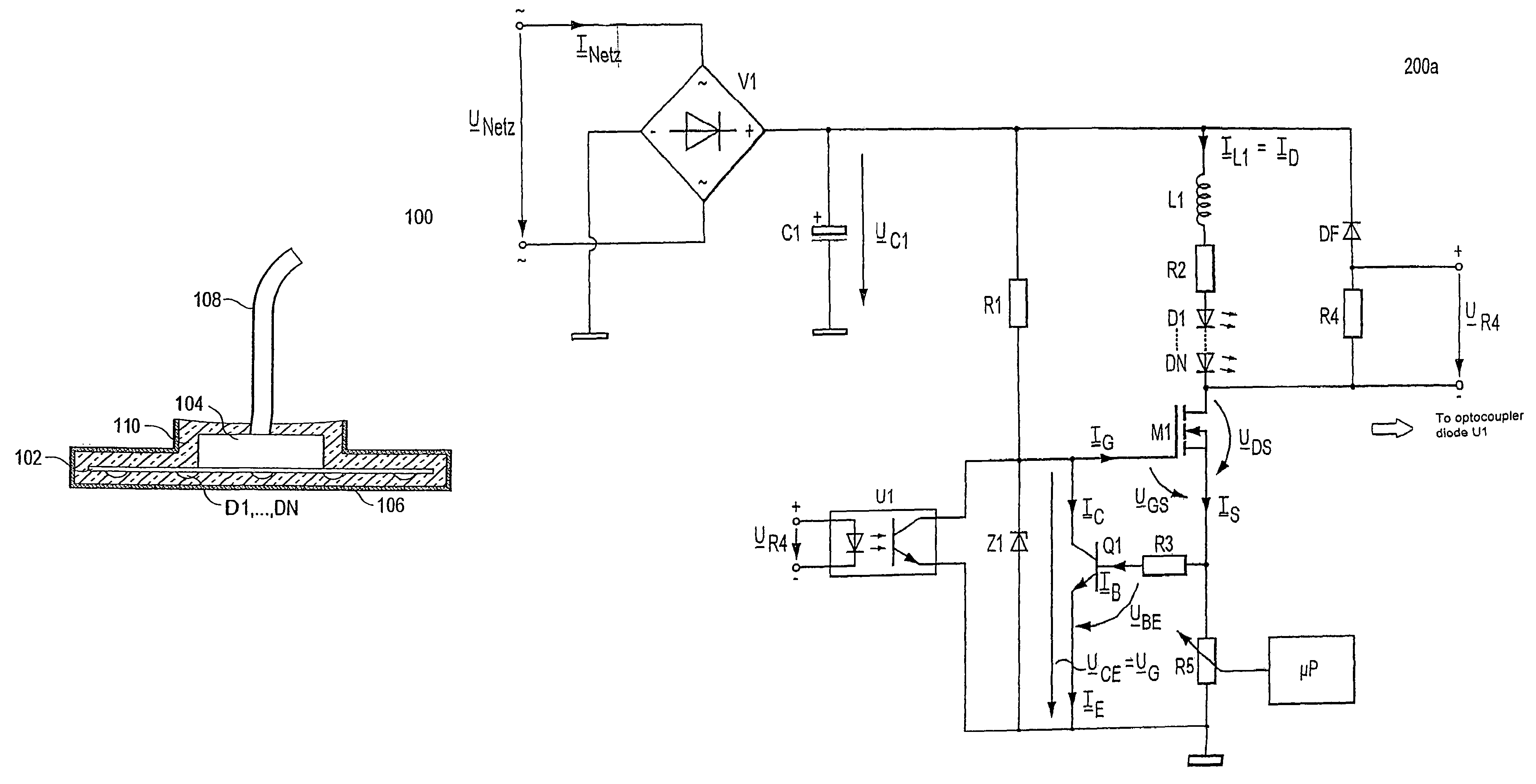
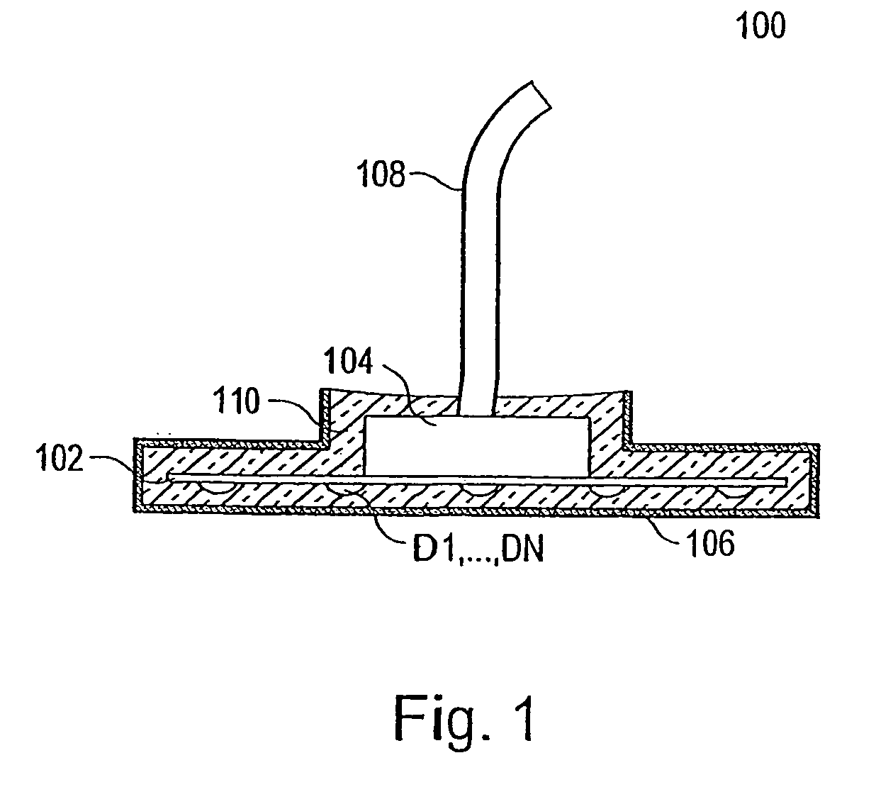
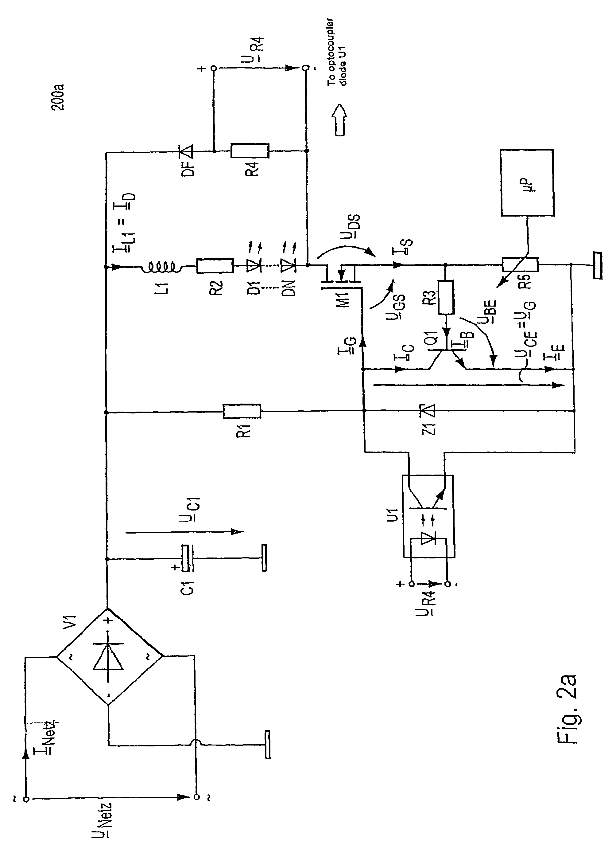
[0024]In the following, the functions of the component groups contained in an exemplary embodiment of the present invention, as illustrated in FIGS. 1 to 3, will be described in more detail. The significance of the symbols provided with reference signs in FIGS. 1 to 3 can be taken from the accompanying list of reference signs.

[0025]In FIG. 1, the basic structure of an LED illumination module 100 is schematically illustrated in longitudinal section. It has an arrangement of luminescent diodes D1, . . . , DN, connected in series, fed with a.c. current, which are applied to a circuit board 102 as so called LED dice in a “Chip-On-Board” (COB) technology.

[0026]However, the invention can just as well be employed for the control of other configurations of LEDs and in particular an individual LED.

[0027]In accordance with an exemplary embodiment of the invention, the heat conducting ceramic circuit board 102 of the LED illumination module 100 has a direct mains current supply, consisting of ...


PUM


Abstract

The present invention is based on a regulation circuit for making available a constant current supply on the basis of a transformer principle, in which there flows through the luminescent diodes (D1, . . . , DN) a triangular a.c. current varying periodically around a DC current value. Both a charging and a discharging current of inductive reactance connected in series to the luminescent diodes (D 1, . . . , DN), functioning as a storage choke for filtering of mains harmonics, flows as diode current through the luminescent diodes (D 1, . . . , DN). According to one exemplary embodiment of the invention the ceramic circuit board of the LED illumination module in accordance with the invention has a direct mains current supply, which for protection from mechanical damage is accommodated in a transparent housing having a highly transparent polymer mass serving as optically active lens surface.

Description

CROSS REFERENCE TO RELATED APPLICATIONS[0001]This Application is a Division of application Ser. No. 11 / 028,297, filed Jan. 4, 2005, which is a Continuation of application PCT / EP03 / 06952 filed on Jun. 30, 2003, and published in German but not English as WO 2004 / 006629 A2 on Jan. 15, 2004, the priority of which is claimed herein (35 U.S.C. §120) and which claims priority of German Application No. 102 30 103.4 filed Jul. 4, 2002, the priority of which is also claimed herein (35 U.S.C. §119).BACKGROUND OF THE INVENTION[0002]1. Field of the Invention[0003]The present invention relates to a current supply for LEDs. Thereby, a transformer principle is put to use which generates a triangular a.c. current, which varies periodically around a d.c. current value, through the luminescent diodes. By means of this process it is provided that both the charging and also discharging current of an inductive reactance in the load circuit flows as diode current through the luminescent diodes.[0004]2. De...

Claims


Application Information

Patent Timeline
Patent Type & Authority Patents(United States)
IPC IPC(8): F21V7/04G05F1/00H05B37/02H05B44/00
CPCH05B33/0803H05B33/0815Y02B20/341Y02B20/30H05B45/36H05B45/382H05B45/375H05B45/56H05B45/10
Inventor TOBLER, FELIXZIMMERMAN, MICHAELTASCH, STEFAN
Owner TRIDONIC OPTOELECTRONICS GMBH
Features
  • R&D
  • Intellectual Property
  • Life Sciences
  • Materials
  • Tech Scout
  • Unparalleled Data Quality
  • Higher Quality Content
  • 60% Fewer Hallucinations
Learn More