Flow cytometer acquisition and detection system

a flow cytometer and detection system technology, applied in the field of flow cytometers, can solve the problems of large system size, poor quantitation, small sample size, etc., and achieve the effects of reducing optical losses, compactness, and facilitating greater coupling efficiency

Active Publication Date: 2010-05-04
ADVANCED CYTOMETRY INSTR SYST
View PDF15 Cites 28 Cited by
  • Summary
  • Abstract
  • Description
  • Claims
  • Application Information

AI Technical Summary

Benefits of technology

[0015]This application describes innovations to a flow cytometer's signal light collection / distribution and detection system which fundamentally change the way signals are detected. There are important new applications stemming from this technology and serious reductions in required space and component costs. The system is flexible in operation, modular and expandable.
[0016]This patent application describes how the image of a flow cell can be focused onto a linear fiber array where each interrogation region is optically coupled with a different input fiber of the linear fiber array. The input fibers are multimode fibers (larger core diameter) and have numerical apertures which are compatible with the light collection and focusing lenses to facilitate greater coupling efficiencies. The individual input fibers are separated and fed into a dispersion module which disperses multiwavelength light signals. These signals are coupled into an array of output fibers, each containing a specific wavelength range, which are then directed to a set of detectors. The proposed arrangement involves fewer optical interfaces, which reduces optical losses, is more compact, more easily reconfigured, more robust, less prone to airborne dust, and can be made less expensively. This method permits time multiplexed signals to be delivered to detectors permitting several unique signals to be measured by a single detector.

Problems solved by technology

While fluorescent microscopy can also examine single cells, the process is usually characterized by small sample sizes, and poor quantitation.
While effective, the system becomes larger in size and more sensitive to misalignments and airborne dust.

Method used


Image

  • Flow cytometer acquisition and detection system
  • Flow cytometer acquisition and detection system
  • Flow cytometer acquisition and detection system

Examples


Embodiment Construction

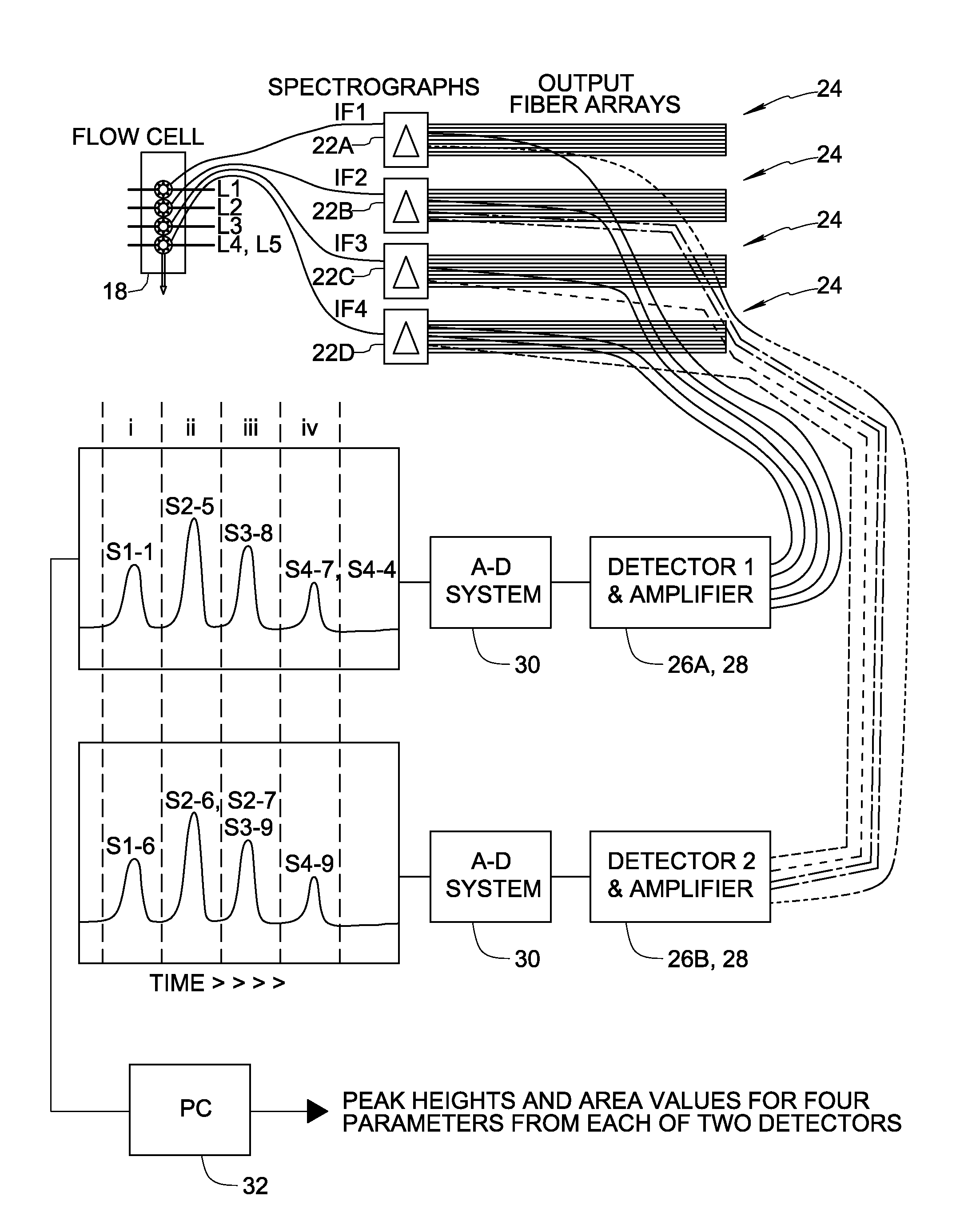
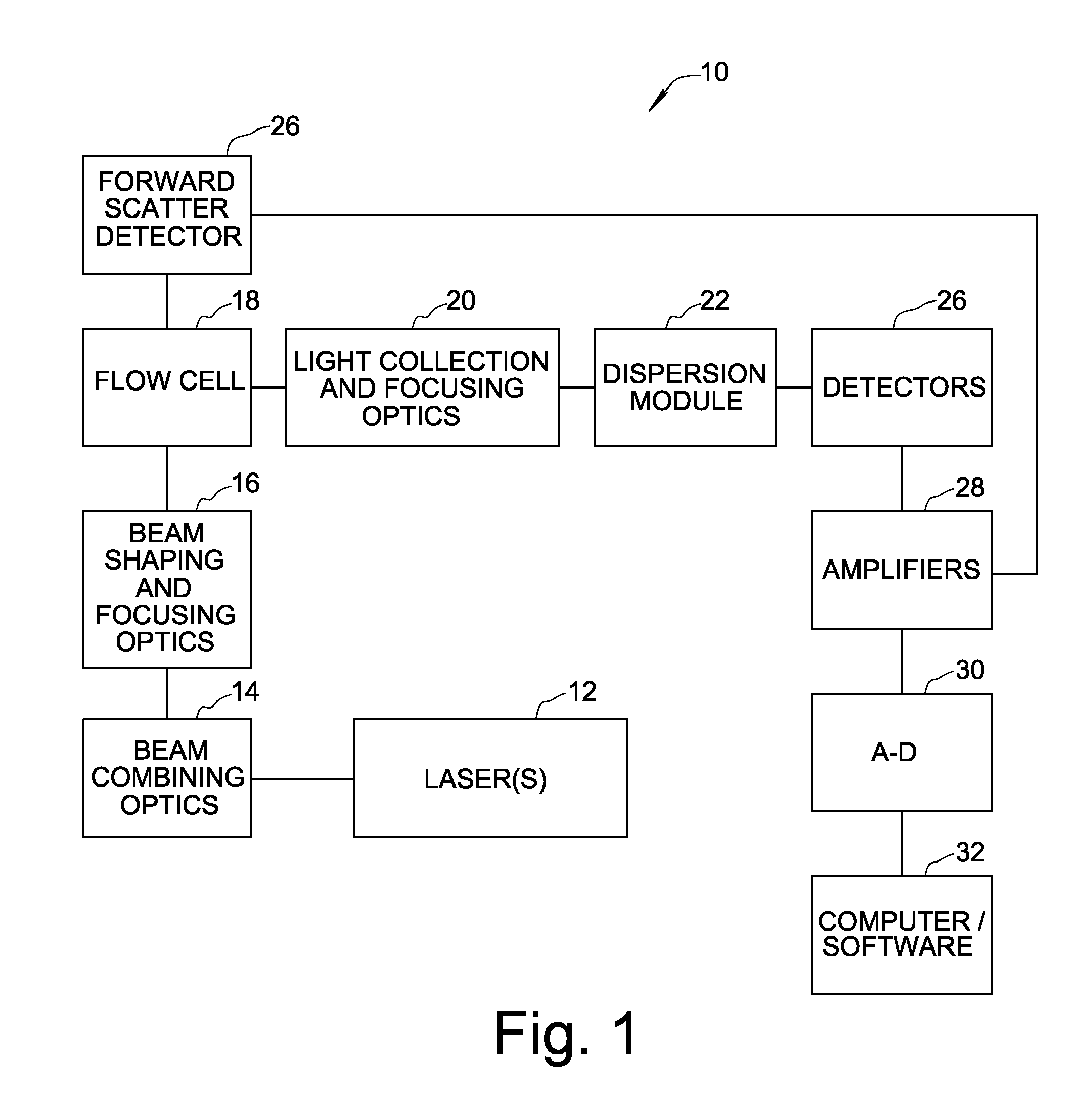
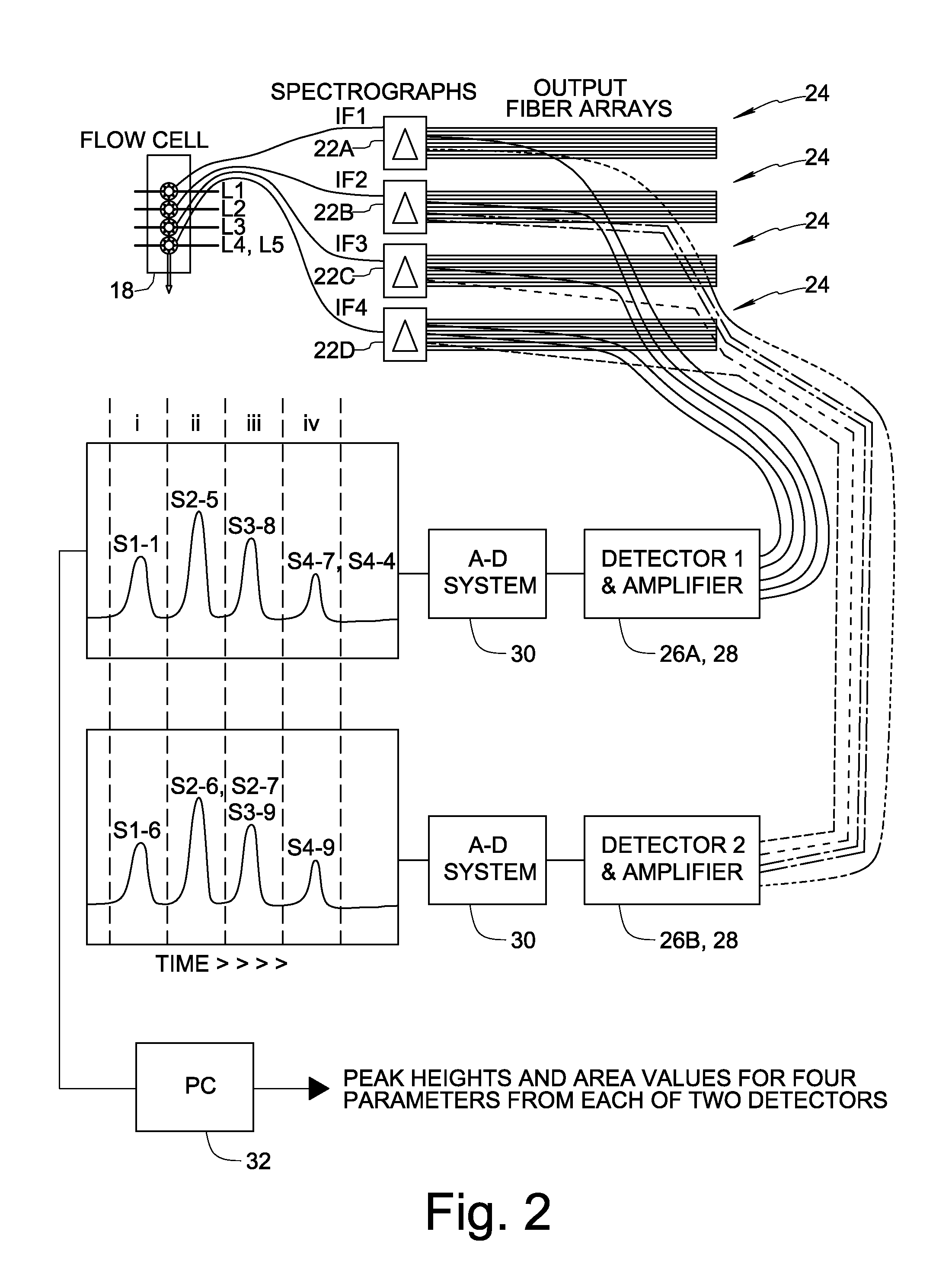
[0031]FIG. 1 is a block diagram of a flow cytometer 10 formed in accordance with an embodiment of the present invention. Flow cytometer 10 comprises one or more lasers 12 used as excitation sources. The use of more than one laser is common. Beam combining optics 14 are typically used to combine the laser beams, and beam shaping and focusing optics 16 are typically provided to direct the laser beams to a stream of cells flowing through a flow cell 18. Laser light is scattered in all directions. Typically, light scattered in the forward direction (forward scatter) gives information different from that scattered at 90 degrees (side scatter). Both forward scatter and side scatter are commonly measured. Side scattered light and omnidirectional fluorescent light are collected and imaged using light collection and focusing optics 20 (primarily lenses) and efficiently coupled into one or more input fibers IF1-IF4 (FIG. 2). In one embodiment of the invention, light is collected from differen...


PUM

PropertyMeasurementUnit
wavelengthsaaaaaaaaaa
emission wavelengthsaaaaaaaaaa

Abstract

A flow cytometer has a flow cell through which a sample flows and at least one laser emitting an excitation beam for illuminating a corresponding interrogation region in the flow cell. Scattered and fluorescence light from each interrogation region is collected by one or more input fibers for that region, and the input fiber(s) are fed to a dispersion module for that interrogation region that disperses the incoming light into different spectral regions. The dispersed light is conveyed, such as by a plurality of output fibers, to one or more photosensitive detectors. Thus, time multiplexed light signals may be delivered to a detector whereby several unique light signals can be measured by a single detector.

Description

CROSS REFERENCE TO RELATED APPLICATIONS[0001]This application claims benefit of U.S. Provisional Application Ser. No. 60 / 675,255 filed Apr. 27, 2005, which is hereby incorporated by reference herein.STATEMENT REGARDING FEDERALLY SPONSORED RESEARCH[0002]This work was supported by Grant No. DE-FG02-01ER83134 from the Department of Energy. The United States Government has certain rights in the invention.FIELD OF THE INVENTION[0003]The invention relates to the field of flow cytometry.BACKGROUND OF THE INVENTION[0004]Flow cytometry is a technique wherein light (usually focused laser beams) of specific wavelengths is used to illuminate cells, beads, macromolecules, etc. as they flow in a narrow stream. Scattered light is collected in the forward and side directions to provide information relating to the size, structure, etc. of the particles.[0005]A common practice in flow cytometry is to employ highly fluorescent dyes to label cells in specific ways. One common method is to attach these ...

Claims


Application Information

Patent Timeline
Patent Type & Authority Patents(United States)
IPC IPC(8): G01N21/49G01J1/58
CPCG01J3/02G01J3/0218G01N21/645G01N15/1459G01N15/1463G01J3/4406
Inventor CASSTEVENS, MARTIN K.BURZYNSKI, RYSZARDWEIBEL, JOHNKACHYNSKI, ALEXANDER
Owner ADVANCED CYTOMETRY INSTR SYST
Why Eureka
Try Eureka