Flow Cytometer Acquisition And Detection System

Active Publication Date: 2006-12-07
ADVANCED CYTOMETRY INSTR SYST
View PDF15 Cites 36 Cited by
  • Summary
  • Abstract
  • Description
  • Claims
  • Application Information

AI Technical Summary

Benefits of technology

[0015] This application describes innovations to a flow cytometer's signal light collection/distribution and detection system which fundamentally change the way signals are detected. There are important new applications stemming from this technology and serious reductions in required space and component costs. The system is flexible in operation, modular and expandable.
[0016] This patent application describes how the image of a flow cell can be focused onto a linear fiber array where each interrogation region is optically coupled with a different INPUT FIBER of the linear fiber array. The INPUT FIBERS are multimode fibers (larger core diameter and have numerical apertures which are compatible with th

Problems solved by technology

While fluorescent microscopy can also examine single cells, the process is usually characterized by small sample sizes, and

Method used


Image

  • Flow Cytometer Acquisition And Detection System
  • Flow Cytometer Acquisition And Detection System
  • Flow Cytometer Acquisition And Detection System

Examples


Embodiment Construction

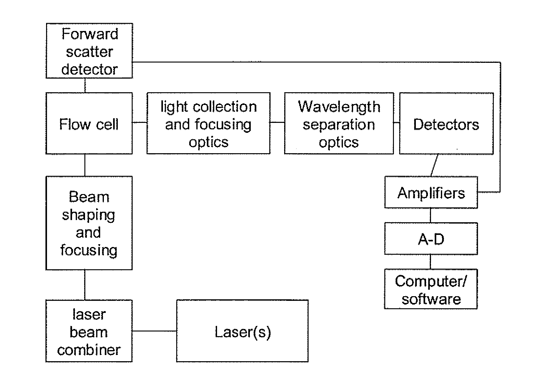
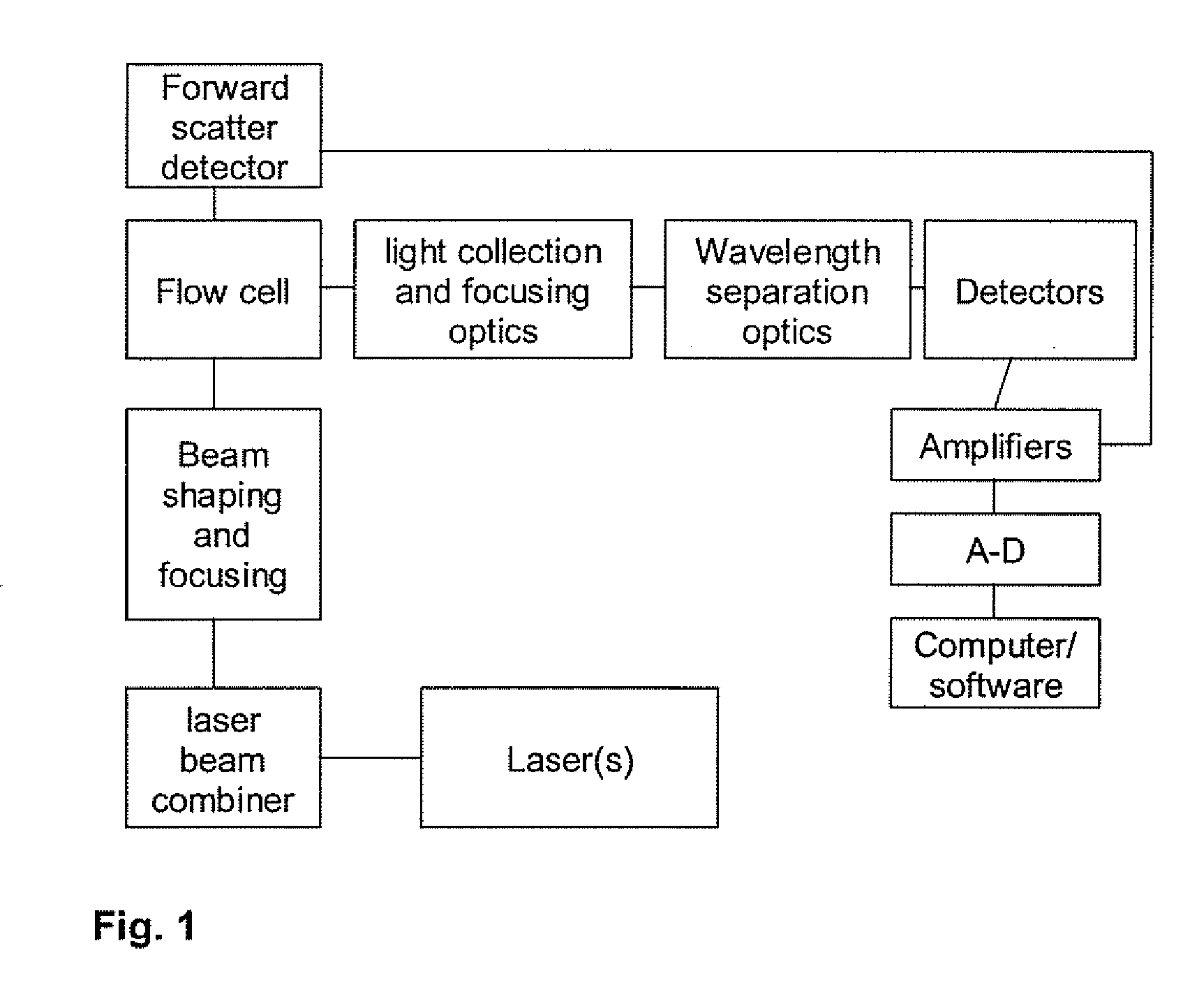
[0020]FIG. 1 is a block diagram of a flow cytometer formed in accordance with an embodiment of the present invention. Lasers (1) are used as excitation sources. The use of more than one laser is common. Optics are typically used to combine the beams (2) and direct them (3) to the stream of flowing cells located in a flow cell (4). Laser light is scattered in all directions. Typically, light scattered in the forward direction (forward scatter) gives information different from that scattered at 90 degrees (side scatter). Both forward scatter and side scatter are commonly measured. Side scattered light and omnidirectional fluorescent light are collected and imaged using a set of optical elements (primarily lenses) (5) and efficiently coupled into an Input Fiber(s). One embodiment of the invention is to collect signal light from different sides of the flow cell in an effort to collect greater amounts of signal. For example, signal light is normally collected at 90 degrees to the directi...


PUM


Abstract

A flow cytometer has a flow cell through which a sample flows and at least one laser emitting an excitation beam for illuminating a corresponding interrogation region in the flow cell. Scattered and fluorescence light from each interrogation region is collected by one or more input fibers for that region, and the input fiber(s) are fed to a dispersion module for that interrogation region that disperses the incoming light into different spectral regions. The dispersed light is conveyed, such as by a plurality of output fibers, to one or more photosensitive detectors. Thus, time multiplexed light signals may be delivered to a detector whereby several unique light signals can be measured by a single detector.

Description

CROSS REFERENCE TO RELATED APPLICATIONS [0001] This application claims benefit of U.S. Provisional Application Ser. No. 60 / 675,255 filed Apr. 27, 2005, which is hereby incorporated by reference herein.STATEMENT REGARDING FEDERALLY SPONSORED RESEARCH [0002] This work was supported by Grant No. DE-FG02-01ER83134 from the Department of Energy. The United States Government has certain rights in the invention.FIELD OF THE INVENTION [0003] The invention relates to the field of flow cytometry. BACKGROUND OF THE INVENTION [0004] Flow cytometry is a technique wherein light (usually focused laser beams) of specific wavelengths is used to illuminate cells, beads, macromolecules, etc. as they flow in a narrow stream. Scattered light is collected in the forward and side directions to provide information relating to the size, structure, etc. of the particles. [0005] A common practice in flow cytometry is to employ highly fluorescent dyes to label cells in specific ways. One common method is to at...

Claims


Application Information

Patent Timeline
IPC IPC(8): G01J1/58
CPCG01J3/02G01J3/0218G01N21/645G01N15/1459G01N15/1463G01J3/4406
Inventor CASSTEVENS, MARTIN K.BURZYNSKI, RYSZARDWEIBEL, JOHN F.KACHYNSKI, ALEXANDER
Owner ADVANCED CYTOMETRY INSTR SYST
Why Eureka
Try Eureka