Catheter imaging probe and method

a catheter imaging and optical coherence tomography technology, applied in catheters, applications, therapy, etc., can solve the problems of myocardial infarction, prone to rupture, no methods are currently available to the cardiologist,

Inactive Publication Date: 2010-05-04
BOARD OF RGT THE UNIV OF TEXAS SYST
View PDF17 Cites 115 Cited by
  • Summary
  • Abstract
  • Description
  • Claims
  • Application Information

AI Technical Summary

Problems solved by technology

Unfortunately, most of us can identify a family member or close friend that has suffered from a myocardial infarction.
Recent evidence from many investigational studies, however, clearly indicate that most infarctions are due to sudden rupture of non-critically stenosed coronary arteries due to sudden plaque rupture.
Unfortunately, no methods are currently available to the cardiologist that may be applied to specify which coronary plaques are vulnerable and thus prone to rupture.
Although treadmill testing has been used for decades to identify patients at greater cardiovascular risk, this approach does not have the specificity to differentiate between stable and vulnerable plaques that are prone to rupture and frequently result in myocardial infarction.
Saline use is limited in duration, however, since myocardial ischemia eventually occurs in the distal myocardium.
Mechanical drag in the rotating shaft can produce significant distortion and artifacts in recorded OCT images of the coronary artery.
Unfortunately, because the catheter will always be forced to make several bends between the entry point in the femoral artery to the coronary artery (e.g., the 180 degree turn around the aortic arch), uneven mechanical drag will result in OCT image artifacts As the application of OCT is shifted from imaging gross anatomical structures of the coronary artery to its capability to image at the level of a single cell, non-uniform rotation of the single fiber OCT prototype will become an increasingly problematic source of distortion and image artifact.
Essentially, current endoscope type single channel OCT systems developed by Light Lab Co. suffers by non-constant rotating speed that forms irregular images of a vessel target.
Their approach of a rotary shaft to spin a single mode fiber is prone to produce artifact.
All these bends will cause uneven friction on the rotary shaft, and uneven time distribution of the light on the entire 360 degree arch of the coronary artery.
As the application of OCT is shifted from gross anatomical structures of the coronary artery to its capability to image at the level of a single cell, then non-uniform rotation of the single fiber OCT will become even a greater source of greater artifact.

Method used


Image

  • Catheter imaging probe and method
  • Catheter imaging probe and method
  • Catheter imaging probe and method

Examples


Embodiment Construction

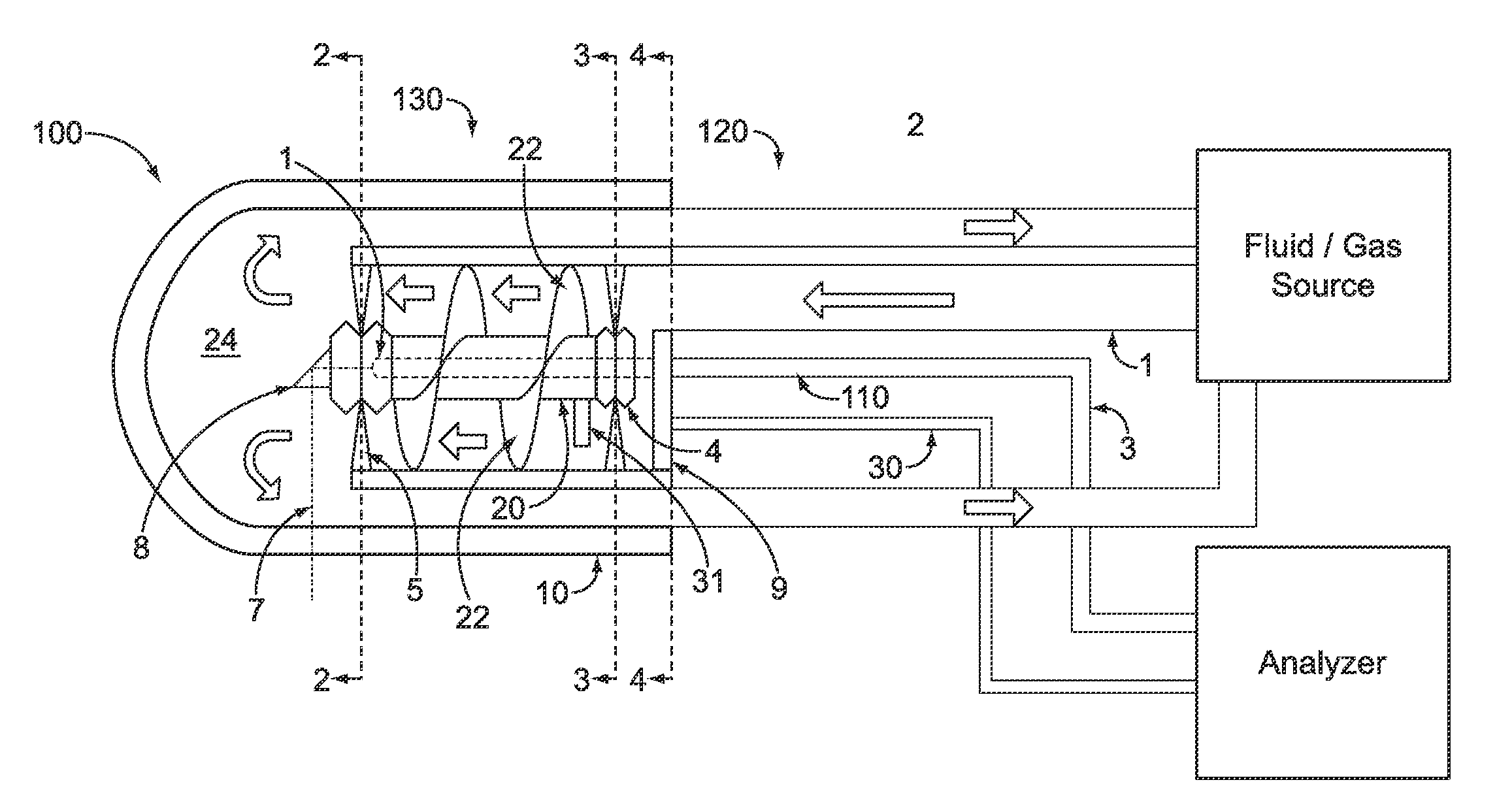
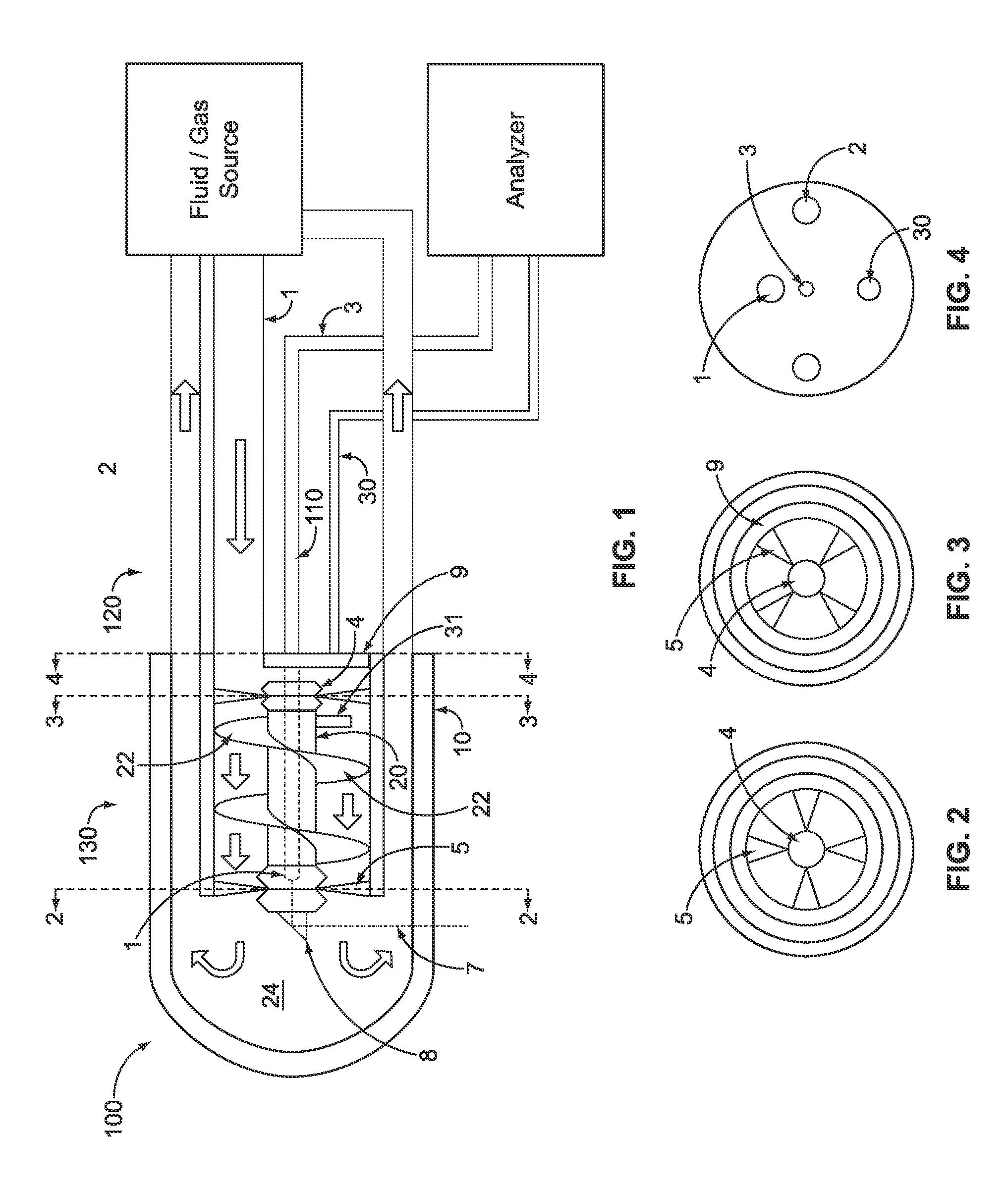
[0032]Referring now to the drawings wherein like reference numerals refer to similar or identical parts throughout the several views, and more specifically to FIG. 1 thereof, there is shown a catheter imaging probe 100 for a patient. The probe 100 comprises a conduit 110 through which energy is transmitted. The probe 100 comprises a first portion 120 through which the conduit 110 extends. The probe 100 comprises a second portion 130 which rotates relative to the conduit 110 to redirect the energy from the conduit 110.

[0033]Preferably, the first portion 120 includes an inlet tube 1 through which fluid flows and wherein the second portion 130 is turned by flowing fluid from the inlet tube 1. The second portion 130 preferably includes a turbine 4 which is turned by the flowing fluid. Preferably, the turbine 4 includes a rotating center shaft 20 through which the conduit 110 extends, and spiral shaped inner grooves 22 which extend from the center shaft 20 that provide a rotating torque ...


PUM


Abstract

A catheter imaging probe for a patient. The probe includes a conduit through which energy is transmitted. The probe includes a first portion through which the conduit extends. The probe includes a second portion which rotates relative to the conduit to redirect the energy from the conduit. A method for imaging a patient. The method includes the steps of inserting a catheter into the patient. There is the step of rotating a second portion of the catheter relative to a conduit extending through a first portion of the catheter, which redirects the energy transmitted through the conduit to the patient and receives the energy reflected back to the second portion from the patient and redirects the reflected energy to the conduit.

Description

CROSS-REFERENCE TO RELATED APPLICATIONS[0001]This application is National Stage Entry of PCT Application Serial No. PCT / US2004 / 12773, filed Apr. 23, 2004, which claims the priority of U.S. Provisional Application Ser. No. 60 / 466,215 file Apr. 28. 2003.FIELD OF THE INVENTION[0002]The present invention relates to optical coherence tomography based on the use of an optical fiber that does not rotate. More specifically, the present invention relates to optical coherence tomography based on the use of an optical fiber that does not rotate that is enclosed in a catheter that has a tip which does rotate to redirect light from the fiber to a surrounding vessel and the light reflected from the vessel back to the optical fiber.BACKGROUND OF THE INVENTION[0003]Myocardial infarction or heart attack remains the leading cause of death in our society. Unfortunately, most of us can identify a family member or close friend that has suffered from a myocardial infarction. Until recently many investiga...

Claims


Application Information

Patent Timeline
Patent Type & Authority Patents(United States)
IPC IPC(8): A61B8/00A61B1/06A61B5/00
CPCA61B5/0066A61B5/6852A61B1/00183A61B8/12A61B8/4461A61B5/0084A61N2007/0091A61B1/3137A61B6/00B82Y99/00
Inventor FELDMAN, MARC D.MILNER, THOMAS E.CHEN, SHAOCHENKIM, JEEHYUNHAN, LI-HSINOH, JUNG-HWANLEE, HO
Owner BOARD OF RGT THE UNIV OF TEXAS SYST
Why Eureka
Try Eureka