Infinitely variable transmission

a transmission machine and variable technology, applied in the direction of gearing elements, belts/chains/gearings, portability lifting, etc., can solve the problems of inability to provide power transmission in both directions, inability to achieve exact synchronisation, and above-prior-art machines are unsuitable. , to achieve the effect of optimal engagemen

Inactive Publication Date: 2010-05-11
VARIBOX IP
View PDF19 Cites 24 Cited by
  • Summary
  • Abstract
  • Description
  • Claims
  • Application Information

AI Technical Summary

Benefits of technology

[0009]An IVT machine according to the invention comprises an input shaft, a drive wheel which is rotatable by the input shaft, an output shaft, a ratio changing device which is mounted coaxially on and rotatable with the output shaft, an endless belt which passes over the drive wheel and in an open loop over ratio changing formations which support the belt loop, on the ratio changing device, control means for causing the ratio changing formations to vary the ratio of rotation of the input and output shafts by enlarging and reducing the belt loop dimension about the output shaft axis on the ratio changing device, belt guide means over which the belt is movable, to provide a throat through which the belt enters and leaves its loop on the ratio changing device, and a drive arrangement which is; located on the ratio changing device for the transmission of drive power to the output shaft, engaged with the belt in a portion of its loop on the device, engageable with the belt on both sides of the throat in its transition across the throat during rotation of the ratio changing device, and maintains optimal engagement with the belt in all ratio positions of the belt loop on the ratio changing device.
[0029]The transversely projecting ends of the chain link pins for use with this form of the machine may be coned at an angle of taper which corresponds to the angle of taper of the ratio changing discs with each conveniently carrying a tapered head which is dimensioned to be a nice fit in the tapered grooves between the ribs. The link pin heads may be slidably engaged on the end portions of the pins and the chain includes outer link arrangements on adjacent pairs of pins which are adapted, in a linear portion of the chain, to expose the coned end portions of the pins from their heads and as the chain enters a curve to progressively move the heads towards the coned ends of the pins to facilitate their entry into and exit from the disc drive arrangement grooves at the chain throat.
[0030]The ratio changing discs in the second and third forms of the invention may each include on their faces opposite their tapered faces an outwardly projecting boss which surrounds the output shaft, a ratio changing gear which is fixed to an externally threaded cylindrical ratio changing gear carrier which is engaged with and freely rotatable on the boss and threadedly engaged with an internally threaded body on the machine frame member so that concomitant rotation of the ratio changing gears will cause the discs to be moved towards and away from each other in dependence on the direction of rotation of the gears. The machine conveniently includes two indexing gears which may be fixed to a common shaft which is journaled for rotation in the machine frame member and are each meshed with a ratio changing gear, a trigger arrangement for snap rotating the indexing gear shaft to cause one or more predetermined partial indexing rotations of the indexing gears and the ratio changing gears in a required direction on demand from the machine controller which simultaneously causes the frame element to be index moved towards or away from the original chain loop between the ratio changing discs as required to supply or remove predetermined lengths of chain to or from the chain loop.

Problems solved by technology

Another problem with these prior art machines is the non-exact synchronisation of their engagement devices with drive chain links where engagement is accomplished via spring-loaded sprocket teeth or rotatable full sprockets operating in the fixed guides which make these devices suitable only for low speed applications, for example on bicycles.
In high speed and high torque applications the above prior art machines are unsuitable.
In the cases of WO03 / 042575 and WO03 / 078869 the synchronisation problems have largely been solved, but they rely on sprag clutches which do not provide for power transmission in both directions (do not allow for engine braking).
In the cases of WO01 / 75333 and U.S. Pat. No. 4,367,067 the positive synchronised engagement of the chain with the disc grooves / ribs again presents a synchronisation problem.
In the cases of WO94 / 04411 and U.S. Pat. No. 5,406,863 positive engagement is accomplished but the storage of the ladder chain as well as its adjustment presents a problem in high speed applications.

Method used


Image

  • Infinitely variable transmission
  • Infinitely variable transmission
  • Infinitely variable transmission

Examples


first embodiment

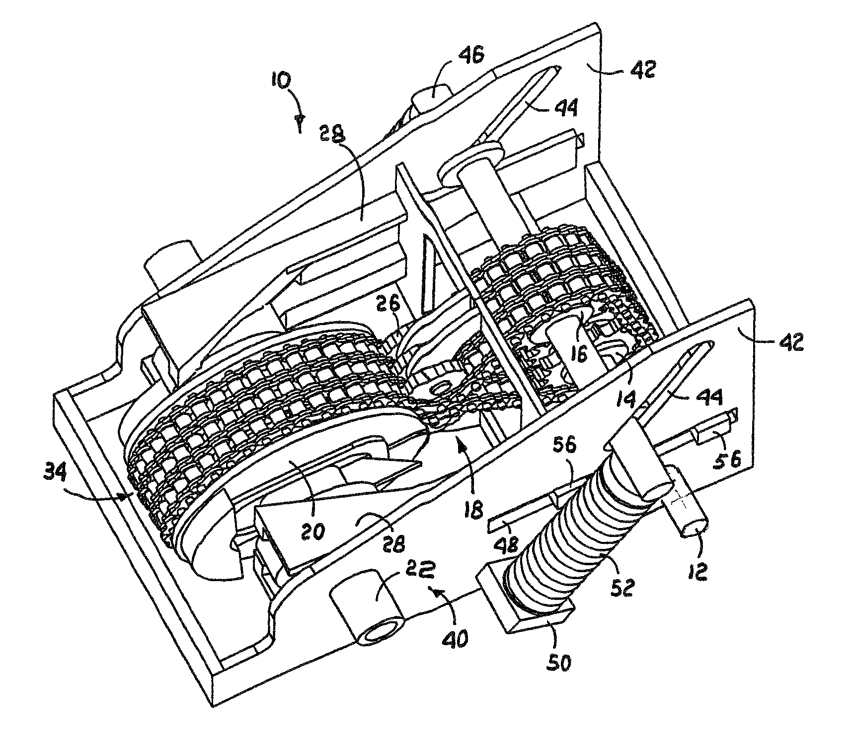
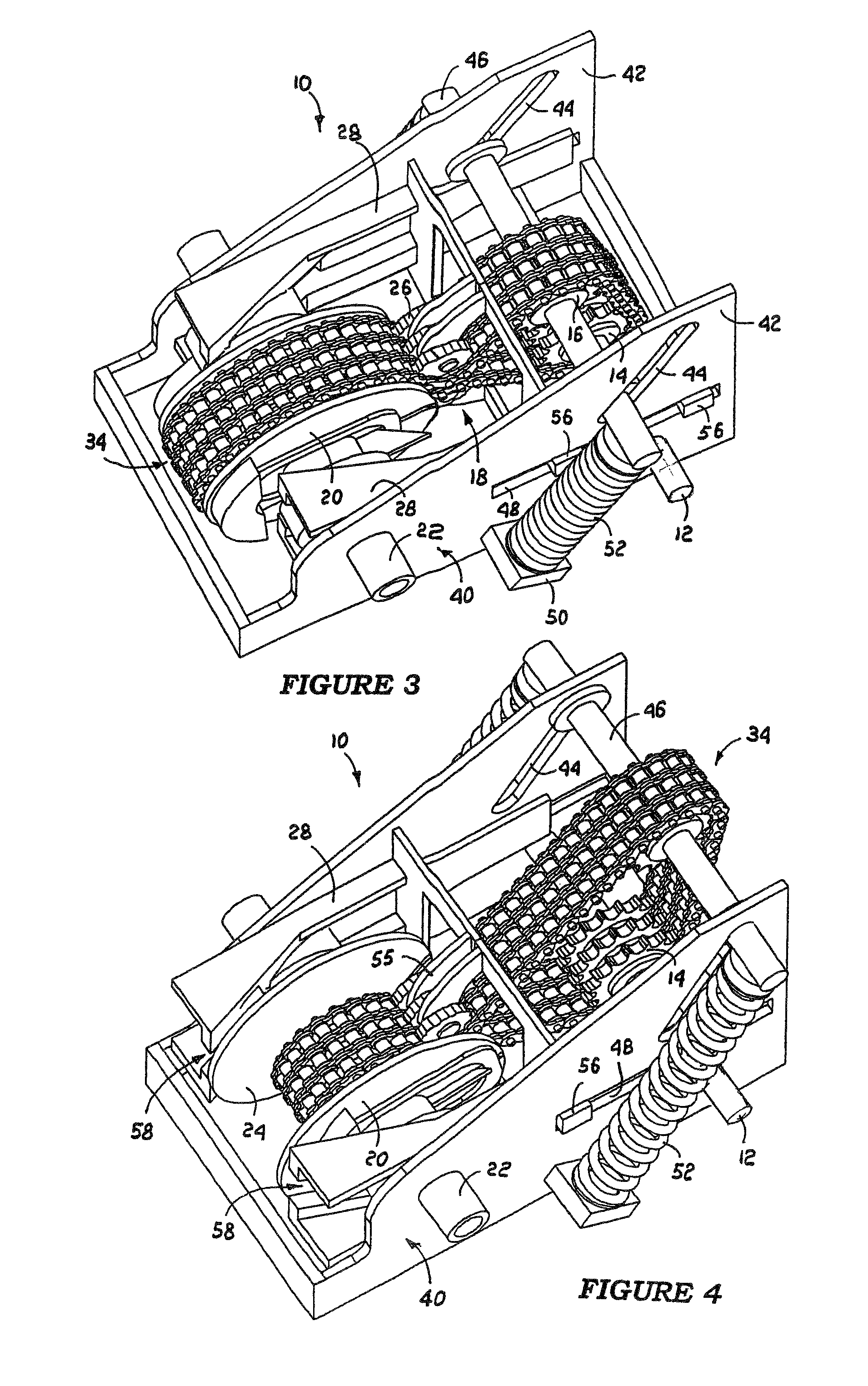
[0086]The practical first embodiment of the machine of FIG. 1 is now described in detail with reference to FIGS. 3 to 12.

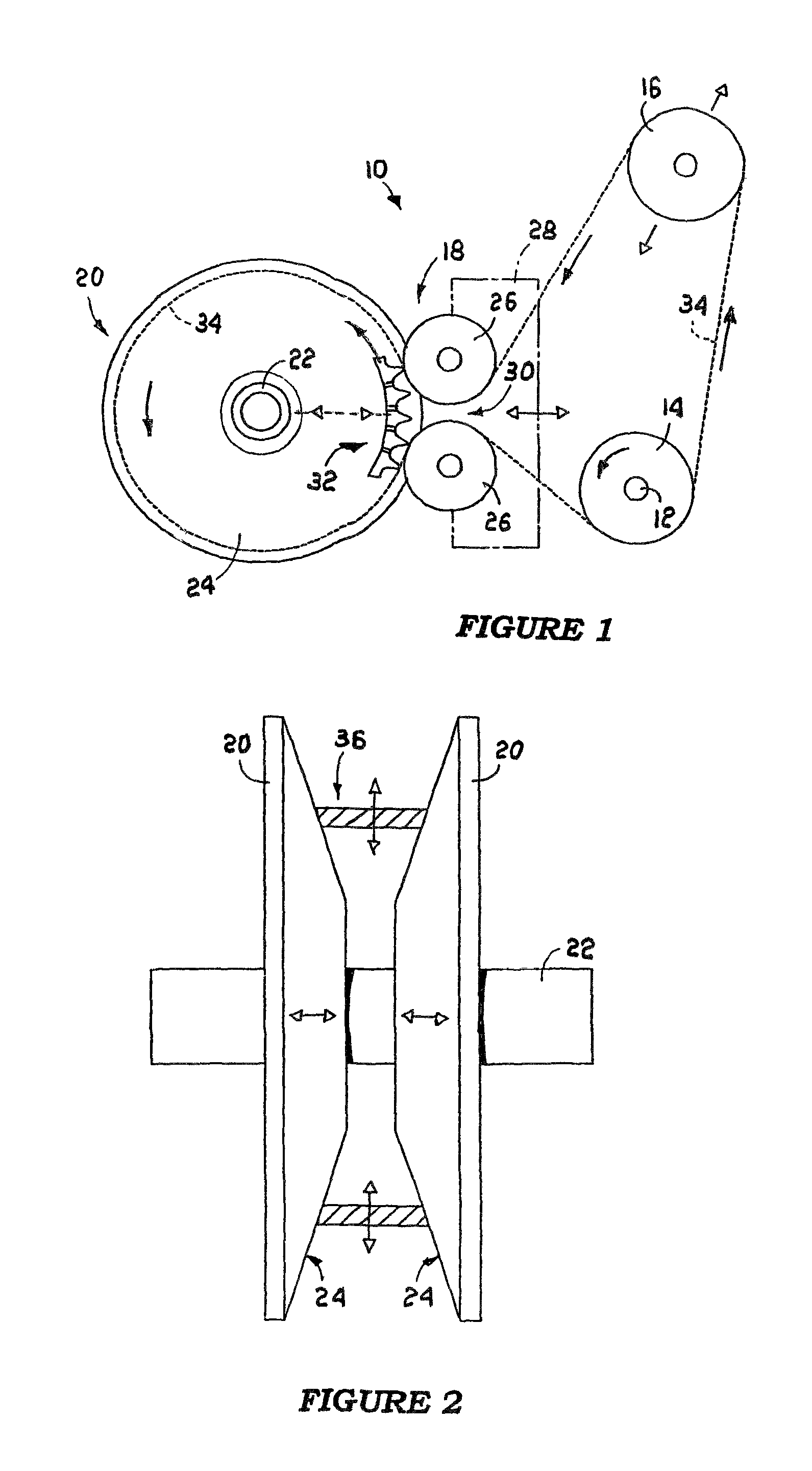
[0087]FIGS. 3 and 4 illustrate the FIG. 1 machine 10 in its low and high ratio positions respectively. In these two drawings the same reference numbers are used as are those in FIG. 1 for the same FIG. 1 machine components.

[0088]The chain 34 is a triple chain with the links of the chains located on common link pins 36 as shown in FIG. 5. The chain links are spaced from each other by rollers 38 on the link pins 36, as shown in FIG. 5. The projecting ends of the link pins 36 are either flattened or coned, with the alternatives shown in FIG. 5, at an angle α which corresponds to the angle of taper of the disc 20 frusto conical faces 24. The tapered pin ends hold the chain wedged against the disc faces at its selected ratio position between the discs against radially inward movement towards the machine output shaft 22. The chain results in triple drive sprockets 14, t...

second embodiment

[0148]In a variation of the FIG. 13 second embodiment of the machine of the invention the chain 34 and the toothed drive arrangement 140 is replaced by the curved chain link chain 184 and the grooved chain engaging drive arrangement bars 186 of FIGS. 20 and 21. As shown in the two drawings, the chain 184 is made up of curved link plates 188 which are pivotally coupled together by link pins 190 which carry spacer rollers 192 which are rotatable between the link plates 188.

[0149]The undersides of the link plates 188 are rounded into a central arch-shaped bar engaging seat formation 194, which is most clearly seen on the central facing link 188 in FIG. 20.

[0150]The ends 195 of the drive arrangement bars 186 are tapered to be complemental to and ride on the tapering bases of the grooves 132, 134 and 136 of the ratio changing disc 128 with the grooves 196 adjacent their ends located in the outer narrower outer portions of the grooves 132 to 136. Only four of the five bars 186 of the mach...


PUM


Abstract

An IVT machine includes an input shaft, a drive wheel on the input shaft, an output shaft, a ratio changing device which is mounted on the output shaft, an endless belt which passes over the drive wheel and in an open loop on the ratio changing device, control elements for enlarging and reducing the belt loop dimension about the output shaft axis, belt guide elements providing a throat through which the belt enters and leaves its loop on the ratio changing device, and a drive arrangement on the ratio changing device for the transmission of drive power to the output shaft and is engaged with the belt in a portion of its loop on the device and engageable with the belt on both sides of the throat in its transition across the throat during rotation of the ratio changing device.

Description

CROSS REFERENCE TO RELATED APPLICATIONS[0001]This application is a continuation-in-part of application Ser. No. 10 / 504,992, which is the 35 USC 371 national stage of international application PCT / ZA2004 / 000023 filed on 5 Mar. 2004, which designated the United States of America, and claimed priority to South African Provisional Patent applications 2003 / 7933 and 2003 / 9224 filed respectively on 13 Oct. 2003 and 27 Nov. 2003. This application also claims foreign priority to South African patent application 2006 / 07143 filed on 25 Aug. 2006. The entire contents of all of these applications are hereby expressly incorporated by reference herein.FIELD OF THE INVENTION[0002]This invention relates to an incrementally operable IVT (infinitely variable transmission) machine which is intended for high power and high angular velocity operation and which is capable of power transmission in a reverse direction through it for engine braking.BACKGROUND TO THE INVENTION[0003]A significant body of prior...

Claims


Application Information

Patent Timeline
Patent Type & Authority Patents(United States)
IPC IPC(8): F16H9/02F16H59/00F16H61/00
CPCF16H9/24
Inventor NAUDE, JOHANNES JACOBUS
Owner VARIBOX IP
Why Eureka
Try Eureka