
Design and execution of a target system that includes a component model

a component model and target system technology, applied in the direction of instruments, cad techniques, analogue processes for specific applications, etc., can solve the problems of high cost to design and execute real systems, limited model provided in the conventional modeling and execution system, and large budgets of engineers, analysts, and researchers in the aerospace and aeronautic industry

Active Publication Date: 2010-05-18
THE MATHWORKS INC
View PDF0 Cites 11 Cited by
  • Summary
  • Abstract
  • Description
  • Claims
  • Application Information

AI Technical Summary

Benefits of technology

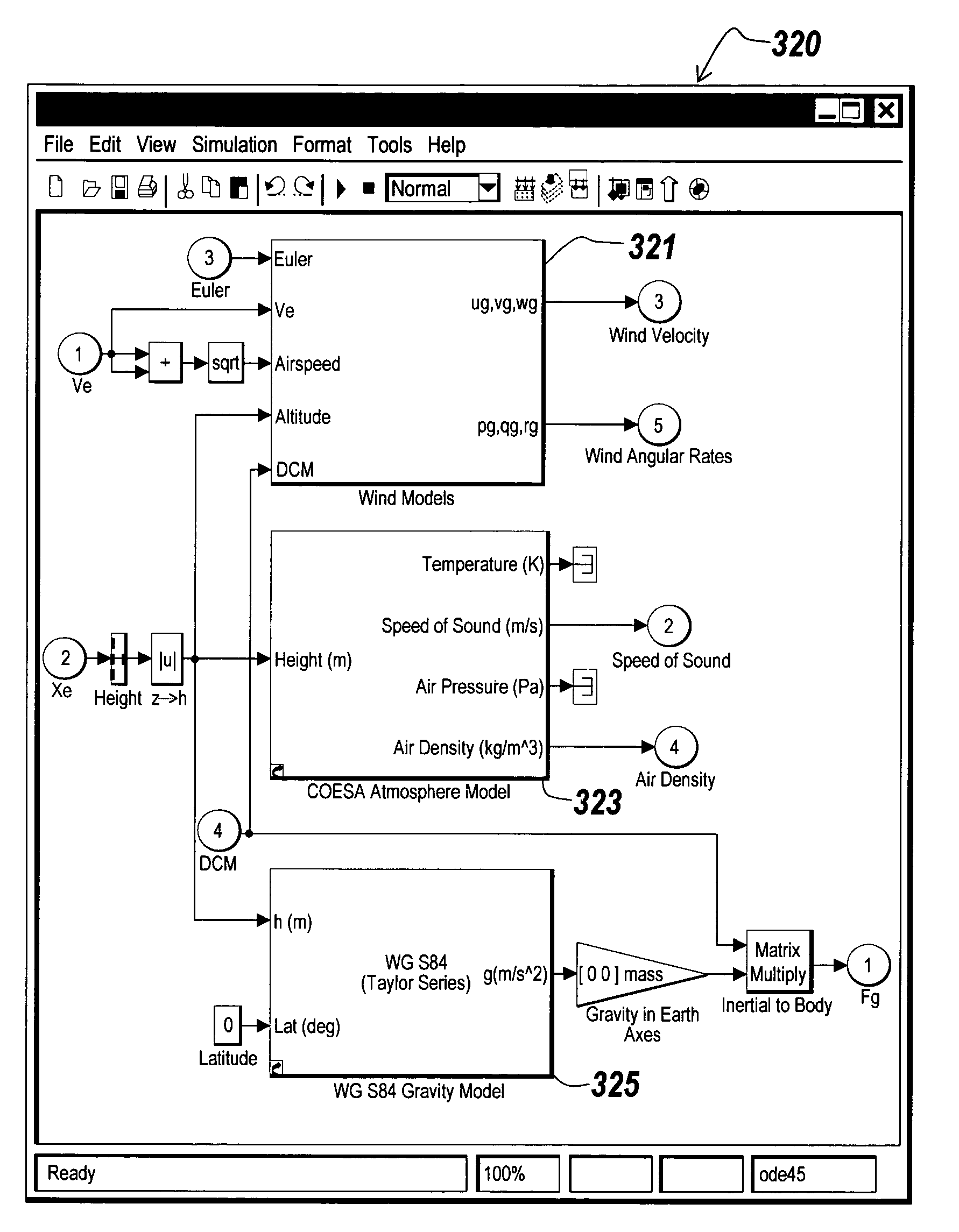
[0010]The present invention provides multiple atmosphere models including standard day atmosphere models and non-standard day atmosphere models. The present invention provides a user interface that displays an option to select one of the atmosphere models. The user interface is provided in response to user's action, such as clicking the symbol representing the atmosphere model. The user interface of the present invention enables users to change a currently incorporated atmosphere model to another atmosphere model without removing the current atmosphere model and then adding another atmosphere model.
[0011]The present invention provides multiple wind turbulence models including continuous wind turbulence models and discrete wind turbulence models. The present invention provides a user interface that displays an option to select one of the wind turbulence models. The user interface is provided in response to user's action, such as clicking the symbol representing the wind turbulence model. The user interface of the present invention enables users to change a currently incorporated wind turbulence model to another wind turbulence model without removing the current wind turbulence model and then adding another wind turbulence model.
[0012]The present invention provides multiple equations of motion models including three-degree-of-freedom (3DoF) equations of motion models and six-degree-of-freedom (6DoF) equations of motion models. The 3DoF and 6DoF equations of motion models may provide models for equations of motion with variable mass. The variable mass includes at least one of simple variable mass in which mass changes via mass rate, and a custom variable mass in which users may specify how the mass changes. The present invention provides a user interface that displays an option to select one of the equations of motion models. The user interface of the present invention enables users to change a currently incorporated equations of motion model to another equations of motion model without removing the current equations of motion model and then adding another equations of motion model.
[0020]By providing standard day atmosphere models and non-standard day atmosphere models, continuous wind turbulence models and discrete wind turbulence models, and models of equations of motion with variable mass, the present invention can design and execute a target system more accurately than the conventional system that provides only standard atmosphere models, continuous wind turbulence models, and fixed mass equations of motion. The present invention enables users to select an atmosphere model conveniently in a user interface that provides an option to select one of atmosphere models. In addition, the present invention also enables users to select a wind turbulence model conveniently in a user interface that provides an option to select one of wind turbulence models. Moreover, the present invention further enables users to select equations of motion model conveniently in a user interface that provides an option to select one of multiple equations of motion models.

Problems solved by technology

Such systems range from simple to highly complex systems.
Engineers, analysts, and researchers in the aerospace and aeronautic industry are often faced with relatively small budgets when designing aerospace and aeronautic systems, such as aircraft, spacecraft, missiles, satellites, weapons, and unmanned airborne vehicles (UAVs).
Computer-based modeling and execution systems are useful in the design of the aerospace and aeronautic systems, which demand high cost to design and execute real systems.
The models provided in the conventional modeling and execution systems are limited to standard day atmosphere models, continuous wind turbulence models, and fixed mass equations of motion models.

Method used


Image

  • Design and execution of a target system that includes a component model
  • Design and execution of a target system that includes a component model
  • Design and execution of a target system that includes a component model

Examples


case ‘ simple

[0112]case ‘Simple Variable’[0113]replaceblock([blk sprintf(‘ / Determine Force, \nMass & Inertia’)], . . . ‘Mass & Inertia (simple)’,‘aerolib3dofsys’);

[0114]case ‘Custom Variable’[0115]replaceblock([blk sprintf(‘ / Determine Force, \nMass & Inertia’)], . . . ‘Mass & Inertia (custom)’,‘aerolib3dofsys’);

[0116]otherwise[0117]error(‘aeroblks:aeroblk3dofbody:invalidtype’,‘mass type not defined’);

end

return

[0118]The user interfaces depicted in FIGS. 4A through 4E may also be applied to display an option to select one of the models provided for other aerospace and aeronautic component, such as actuators 215 and propulsion 214 models. For example, the user interface may be used to enable users to change a currently incorporated actuator model to another actuator model, or to change a currently incorporated propulsion model to another propulsion model. In these applications, the models provided in the user interface for the users to select may be extended by the users so that the users may add m...


PUM


Abstract

Methods and systems for the design and execution of an aerospace or aeronautic system are provided. The aerospace or aeronautic system may incorporate planetary environment models and models of equations of motion. The planetary environment models mathematically represent planetary environment specifications, such as atmosphere and wind. Atmosphere models include standard day atmosphere models and non-standard day atmosphere models, and wind models include continuous wind turbulence models and discrete wind turbulence models. The models of equations of motion include models of three-degree-of-freedom equations of motion with variable mass and models for six-degree-of-freedom equations of motion with variable mass. As a result, the present invention can design and execute a target system more accurately than the conventional system that provides only standard day planetary environment models, continuous wind turbulence models, or fixed mass equations of motion models.

Description

FIELD OF THE INVENTION[0001]The present invention relates generally to block diagram execution environments and more particularly to methods and systems for the design and execution of a target system that includes a component model.BACKGROUND OF THE INVENTION[0002]Computer systems may include interactive software tools that provide environments for designing and executing digital models of electrical, electronic or mechanical devices prior to producing actual physical devices. The design and execution of a target system is performed on computers using the software tools, such as Simulink® and MATLAB®, both from The MathWorks Inc. of Natick, Mass.[0003]Various classes of block diagrams describe computations that can be performed on application specific computational hardware, such as a computer, microcontroller, FPGA, and custom hardware. Classes of such block diagrams include time-based block diagrams such as those found within Simulink from the MathWorks, Inc. of Natick Mass., sta...

Claims


Application Information

Patent Timeline
IPC IPC(8): G06G7/48
CPCG06F17/5009G06F2217/80G06F2217/16G06F2119/08G06F2111/10G06F30/20
Inventor GAGE, STACEY M.
Owner THE MATHWORKS INC
Learn More