Travelling carrier delivery equipment

a technology of transportation carrier and equipment, applied in the direction of runways, charge manipulation, furniture, etc., can solve the problems of complex control system, high facility cost, unpractical in terms of facility cost, etc., and achieve the effect of low cost, reliable performance and convenient operation

Inactive Publication Date: 2010-05-25
DAIFUKU CO LTD
View PDF8 Cites 9 Cited by
  • Summary
  • Abstract
  • Description
  • Claims
  • Application Information

AI Technical Summary

Benefits of technology

[0017]In addition, an auxiliary rail (158) that can freely open and close and fills a space between a movable rail (106) and a main rail (157) to which the movable rail (106) is connected can be provided on the end of the movable rail (106). It is possible that the auxiliary rail (158) is pivotally supported on an end of the movable rail (106) so as to swing vertically, and drive means (160) that switches this auxiliary rail (158) between a standing open posture and a use posture in which the auxiliary rail (158) is connected to a main rail (157) is provided, and on this auxiliary rail (158) and the main rail (157), vertical fitting portions (174a, 174b, 175) that fit with each other when the auxiliary rail (158) is switched to the use posture in which it is connected to the main rail (157) and prevents leftward and rightward horizontal displacements of these rails (157, 158) are provided.
[0027]Furthermore, to prevent contact between the movable rail and a main rail even if movement of the movable rail involves slight shaking, the space between the moving path of the movable rail and the main rail can be made sufficiently large, and transferring of the travelling carrier between the movable rail and the main rail to which the movable rail is connected can be reliably performed. In this case, according to the constitution described in claim 16, positional displacement in the left and right horizontal direction between the movable rail and the main rail to which the movable rail is connected can be prevented by using the posture switching of the auxiliary rail, whereby the transferring of the travelling carrier between the rails can be more safely and more reliably performed.

Problems solved by technology

As described above, in such a conventional type of travelling carrier delivery equipment, a friction drive wheel is necessary not only on the movable rail side but also on each travelling path side to which this movable rail is connected, and in addition, control of the friction drive wheel on each travelling path side is also necessary, so that the control system becomes complicated, and as a whole, the facilities cost becomes very high.
Particularly, in travelling carrier delivery equipment for storage in which a number of storage rails for storing a number of travelling carriers are arranged parallel, and the movable rail traverses and is connectable to an arbitrary storage rail, the friction drive wheel must be provided for each of all storage rails, and this is not practicable in terms of the facilities cost.
Of course, travelling carrier delivery equipment constituted so as to transfer a travelling carrier by pushing and pulling drive means on the movable rail side is also considered, however, in the case of equipment that handles travelling carriers with long entire lengths for carrying long objects, the stroke of a lock tool on the pushing and pulling drive means side that engages with a locked portion of the travelling carrier side also becomes longer according to the entire length of the travelling carrier, the pushing and pulling drive means becomes large in size and complicated, and this is still impractical.

Method used


Image

  • Travelling carrier delivery equipment
  • Travelling carrier delivery equipment
  • Travelling carrier delivery equipment

Examples


first embodiment

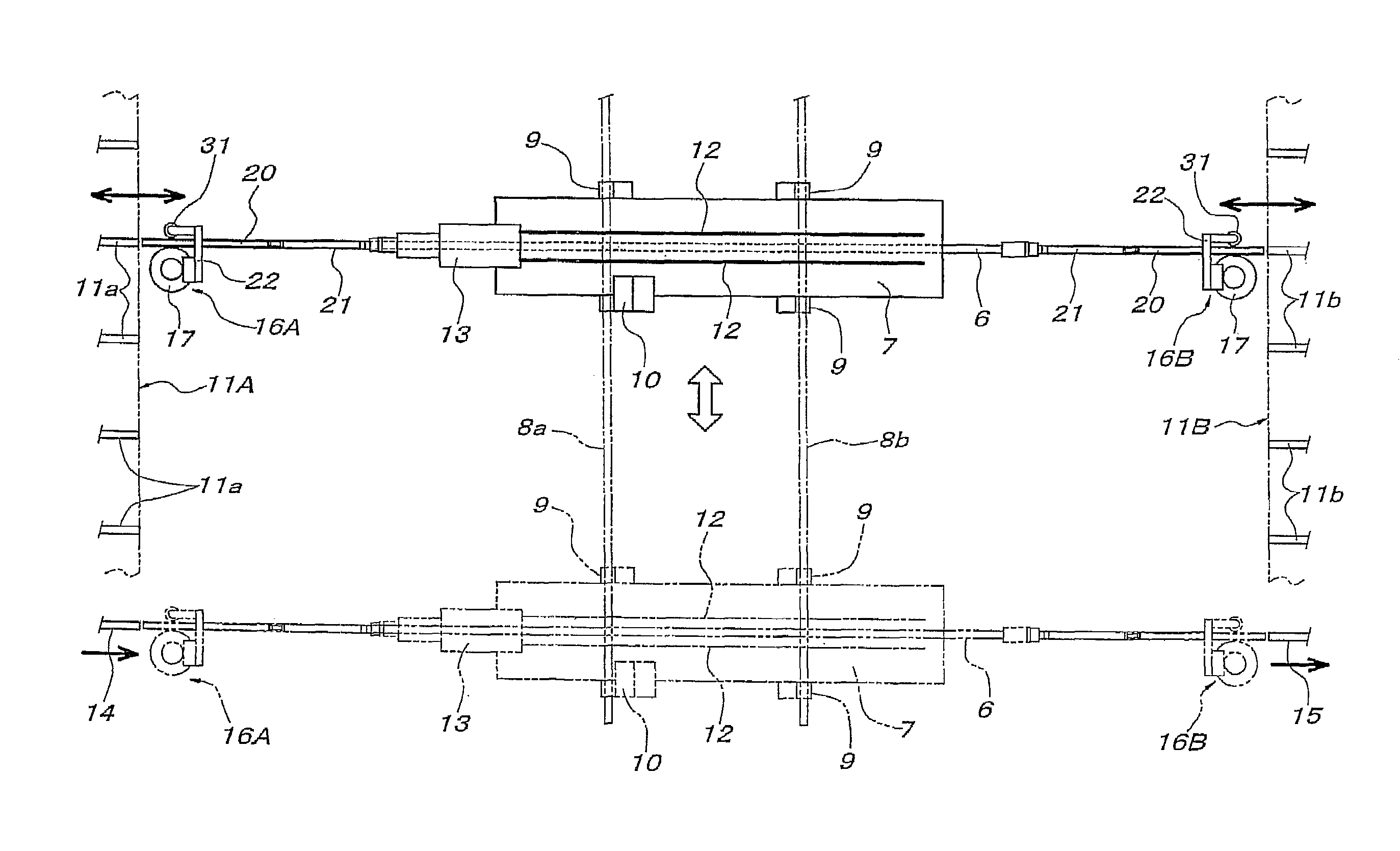
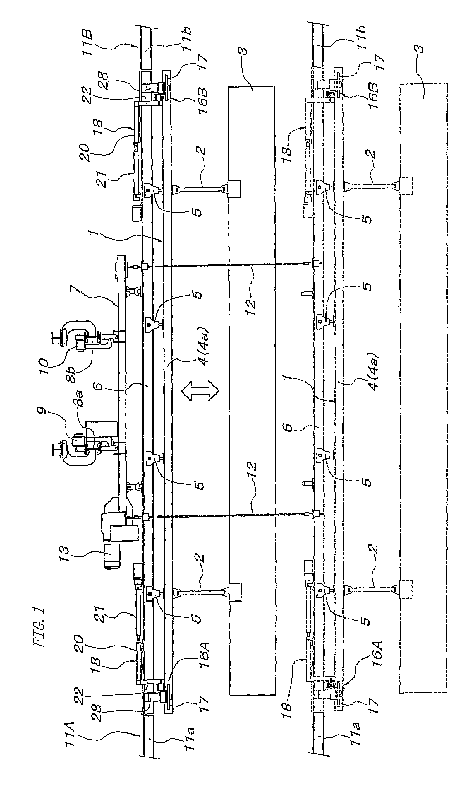
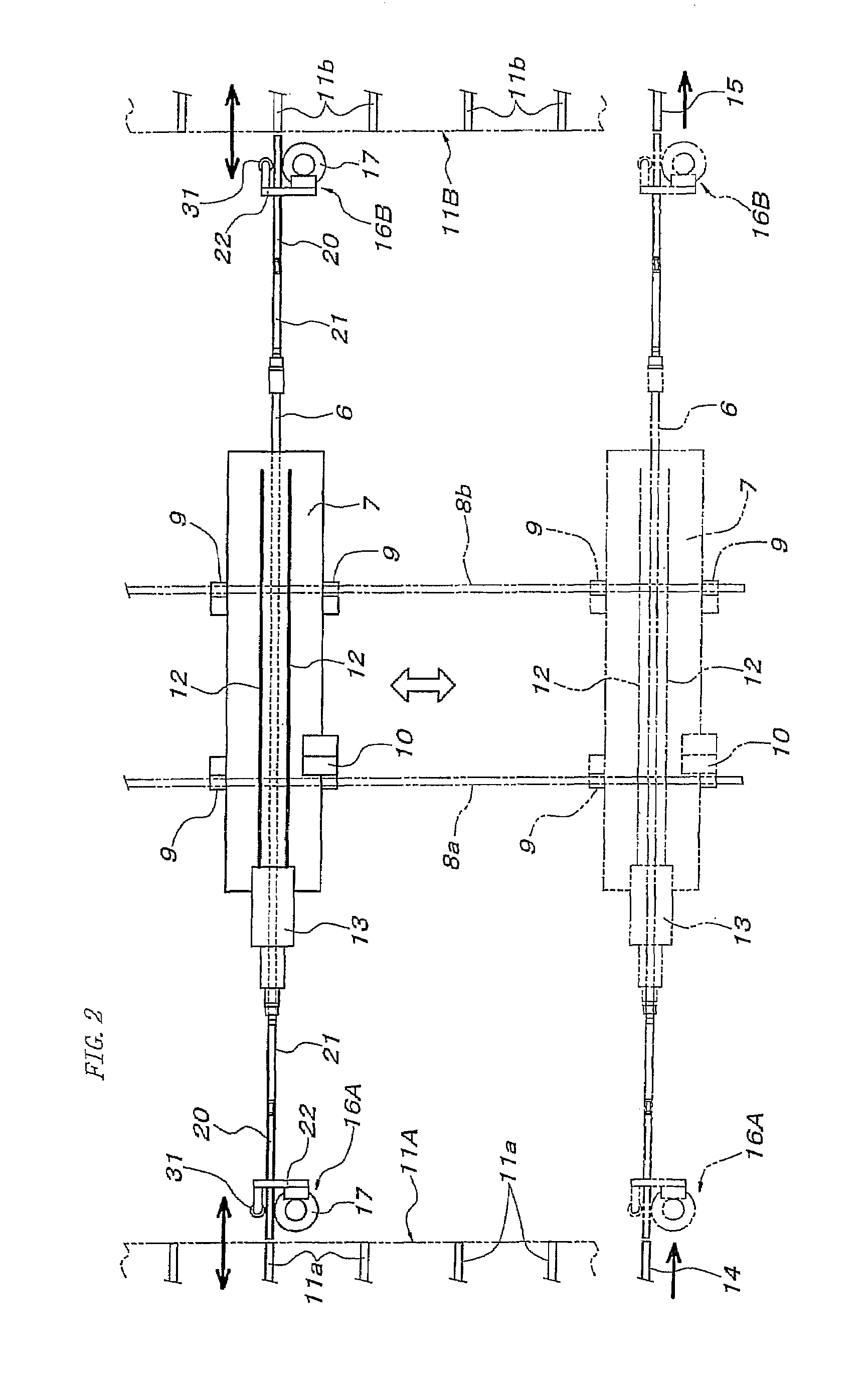
[0122]Hereinafter, the invention will be described based on FIG. 1 through FIG. 5. In FIG. 1 and FIG. 2, the reference numeral 1 denotes a travelling carrier having a load bar 4 for hanging a long carried object 3 via hangers 2, and trolleys 5 attached to both ends and a plurality of intermediate points of the load bar 4. In the figures, the trolleys 5 on both ends are not shown and the load bar 4 is simply shown as one bar-like member, however, in actuality, as conventionally known, the load bar is divided so as to be bent at least horizontally around a vertical axis at a plurality of points (for example, at positions of the trolleys 5) in the length direction.

[0123]The reference numeral 6 denotes a movable rail which has an entire length almost equal to the entire length of the travelling carrier 1 (load bar 4) and on which one travelling carrier 1 can be hung down movably via the trolleys 5. The reference numeral 7 denotes a movable rail hanging mobile body (hereinafter, abbrevia...

second embodiment

[0142]the invention will be described with reference to FIG. 7 through FIG. 14. In FIG. 7 and FIG. 8, 101 denotes a travelling carrier having a load bar 104 for hanging a long carried object 103 via hangers 102 and trolleys 105 attached to both ends and a plurality of intermediate points of this load bar 104. The load bar 104 is divided so as to be bent at least horizontally around a vertical axis at a plurality of points (positions of the trolleys 105) in the length direction as conventionally known.

[0143]The reference numeral 106 denotes a movable rail, which has an entire length almost equal to the entire length of the travelling carrier 101 (load bar 104) (in the illustration, an entire length slightly longer than the entire length of the load bar 104), and can hang one travelling carrier 101 movably via the trolleys 105. The reference numeral 107 denotes a movable rail hanging mobile body (hereinafter, abbreviated to mobile body) for hanging the movable rail 106 down, and is a ...

fourth embodiment

[0173]When the travelling carrier delivery end between the movable rail and the main rail 157 is only one end of the movable rail 106, of course, the delivery unit is disposed on only the travelling carrier delivery end side of the movable rail 106, however, even when both ends of the movable rail 106 become travelling carrier delivery ends between the same and the main rail, as in the fourth embodiment whose outline constitution is shown in FIG. 21, the one friction drive wheel 124 is formed so as to reciprocate between one retreating position R at which the friction drive wheel comes into contact with the central position of the entire length of the friction driving surface 104a of the travelling carrier 101 supported on the movable rail 106 and a first forwarding position F1 at which the friction drive wheel comes into contact with a position near the movable rail side end of the friction driving surface 104a of the travelling carrier 101 supported on the main rail 157A to be con...


PUM


Abstract

Travelling carrier delivery equipment includes a delivery unit for transferring a travelling carrier that has no self-running means between a movable rail and a main rail by means of external friction-driven, and the travelling carrier is provided with a friction driving surface across its entire length, the delivery unit has a friction drive wheel and friction drive wheel moving means, the friction drive wheel is provided on the movable rail and is switchable between a driving state, in that it propels the travelling carrier via the friction driving surface and a driving release state, and the friction drive wheel moving means reciprocates the friction drive wheel between a retreating position (R), at which the friction drive wheel can be made to contact with the friction driving surface of the travelling carrier supported on the movable rail and a forwarding position (F), at which the friction drive wheel can be made to contact with the friction driving surface of the travelling carrier supported on the main rail.

Description

RELATED APPLICATIONS[0001]This is a continuation of PCT Application No. PCT / JP2006 / 311991, filed Jun. 15, 2006, pending.FIELD OF THE INVENTION[0002]The present invention relates to delivery equipment including delivery units for transferring a travelling carrier that has no self-running means between a main rail and a movable rail connectable to the main rail by means of external friction-driven.BACKGROUND OF THE INVENTION[0003]This type of travelling carrier delivery equipment is utilized as means for switching a travelling path of a travelling carrier, means for distributing travelling carriers to a plurality of storage branch lines from a main line as a main travelling path of the travelling carrier and returning the travelling carriers to the main line from storage branch lines, or means for reversing the front and rear direction of a travelling carrier in the middle of a travelling path of the travelling carrier. For example, the travelling carrier delivery equipment described ...

Claims


Application Information

Patent Timeline
Patent Type & Authority Patents(United States)
IPC IPC(8): B65G43/08
CPCB61B13/127B65G1/0442B66C7/12B65G35/06B65G1/0457B65G39/025
Inventor TAKANO, RYOSUKENISHIHARA, SHIGEYOSHI
Owner DAIFUKU CO LTD
Why Eureka
Try Eureka