CMC to metal attachment mechanism

a technology of metal attachment mechanism and clamping mechanism, which is applied in the direction of fastening means, blade accessories, machines/engines, etc., can solve the problems of less strain tolerance, wear and/or fatigue, and less brittle nature than metal

Inactive Publication Date: 2010-05-25
SIEMENS ENERGY INC
View PDF18 Cites 38 Cited by
  • Summary
  • Abstract
  • Description
  • Claims
  • Application Information

AI Technical Summary

Problems solved by technology

However, attaching low alpha (low thermal growth) CMCs to higher alpha metals is not a simple procedure.
In dynamic environments, the CMC and metal need to be rigidly attached to prevent vibration, which may lead to wear and / or fatigue issues.
CMC is by nature more brittle and less strain-tolerant than metal.
Such movement could damage, or even destroy, the CMC.

Method used


Image

  • CMC to metal attachment mechanism
  • CMC to metal attachment mechanism
  • CMC to metal attachment mechanism

Examples


Embodiment Construction

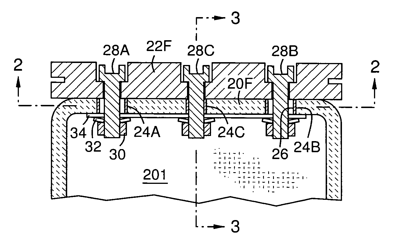
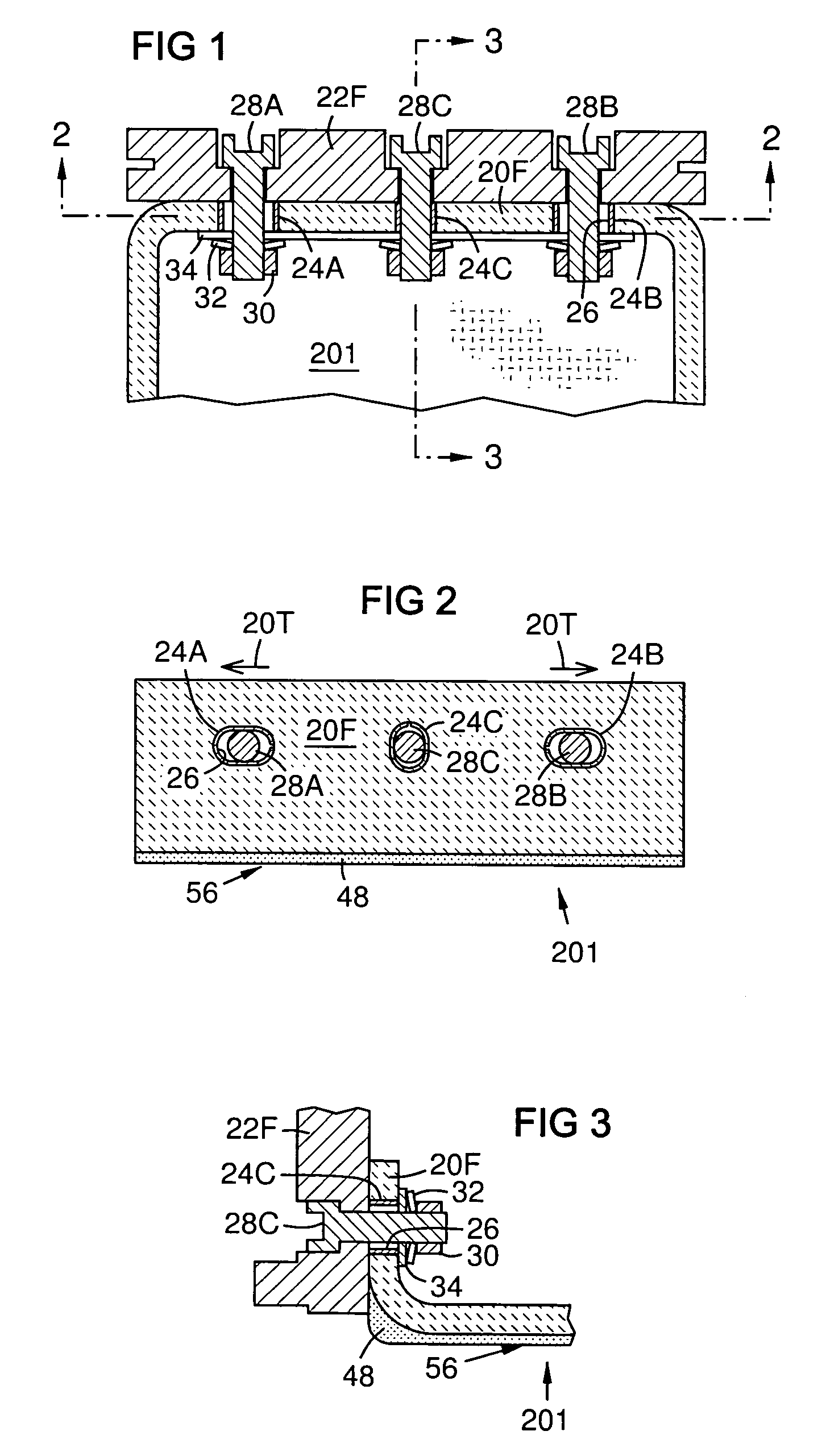
[0017]The first design consideration in the attachment of a CMC component to a metal component in a dynamic, high temperature environment is how to clamp the CMC hard enough against the metal to prevent relative vibratory motion while still allowing for the two components to grow different amounts due to temperature changes. FIG. 1 shows such a solution. A CMC component 201 has a wall 20F that is mounted against a metal wall 22F by three bolts 28A, 28B, and 28C. A nut 30 on each of the bolts 28A, 28B, 28C clamps the CMC wall 20F against the metal wall 22F with a retaining force in a range between a lower limit below which sliding is present between the CMC wall 20F and the metal wall 22F due to operational vibrations in the CMC and metal components 201, 22F, and an upper limit above which it prevents relative sliding of the walls 20F, 22F due to differential thermal expansion or above which it exceeds a stress limit in the CMC wall 20F, the range being non-inclusive of the upper and...


PUM

PropertyMeasurementUnit
clamping stressaaaaaaaaaa
thermal expansionaaaaaaaaaa
elongationaaaaaaaaaa

Abstract

A CMC wall (20F) may be attached to a metal wall (22F) by a plurality of bolts (28A, 28B, 28C) passing through respective holes (24A, 24B, 24C) in the CMC wall (20F) and holes in the metal wall (22F), clamping the walls (20F, 22F) together with a force that allows sliding thermal expansion but does not allow vibrational shifting. Distal ones of the holes (24A, 24B) in the CMC wall (20F) or in the metal wall (22F) are elongated toward a central one of the bolts (24C) or at alternate angles to guide differential thermal expansion (20T) of the CMC wall (20F) versus the metal wall (22F) between desired cold and hot geometries. A second CMC wall (20R) may be mounted similarly to a second metal wall (22R) by pins (39A, 39B, 39C) that allow expansion of the CMC component (201) in a direction normal to the walls (20F, 20R).

Description

FIELD OF THE INVENTION[0001]The invention relates to mechanisms for attaching low alpha ceramic components to high alpha metal support structures in high temperature, dynamic environment, in particular in industrial and aero gas turbines.BACKGROUND OF THE INVENTION[0002]Ceramic matrix composites (CMCs) have a higher temperature capability than metallic alloys, making them potentially very valuable for implementation into gas turbines, which can run at temperatures well in excess of metal capabilities. Metal is stronger and more ductile, making it better for supporting hardware, such as vane carriers, casings, bolting, etc. To combine the advantages of these two materials, at some point they must attach to one another. However, attaching low alpha (low thermal growth) CMCs to higher alpha metals is not a simple procedure. In dynamic environments, the CMC and metal need to be rigidly attached to prevent vibration, which may lead to wear and / or fatigue issues. But, if high temperatures...

Claims


Application Information

Patent Timeline
Patent Type & Authority Patents(United States)
IPC IPC(8): F01D25/26
CPCF01D25/246Y10T29/49321F05D2300/603F05D2300/21F16B5/0241
Inventor SCHIAVO, ANTHONY L.KELLER, DOUGLAS A.GONZALEZ, MALBERTO F.RADONOVICH, DAVID C.
Owner SIEMENS ENERGY INC
Why Eureka
Try Eureka