Sensor-based chemical management for agricultural landscapes

a sensor-based chemical and agricultural technology, applied in the field of crop canopy light sensors, can solve problems such as the limitation of the method of use, and achieve the effect of minimizing the extra management steps and overhead, and optimizing the application of an agrochemical

Active Publication Date: 2010-05-25
KYLE H HOLLAND TRUSTEE OF THE MARANATHA TRUST DATED JULY 30 2013
View PDF26 Cites 57 Cited by
  • Summary
  • Abstract
  • Description
  • Claims
  • Application Information

AI Technical Summary

Benefits of technology

[0013]The present invention provides several methods for practicing sensor-based precision farming techniques pertaining to the application of materials such as seeds, fertilizer, pesticides, herbicides or other agricultural substances. In contrast to prior techniques, the preferred embodiment does not utilize a highly fertilized reference area (or controlled agrochemical region whether it be treated with a high or low dose of material) to calibrate the sensing system for application of an agrochemical and thereby eliminates the extra management steps and overhead required by the producer to create, locate and maintain these portions of a field. This is advantageous because a major hurdle hindering the adoption of remote sensing technology for variable rate agrochemical application pertains to the requirement of creating a known calibration standard within the field in order to differentially compare measurements obtained for the control section to other non control portions of the field. Growers and spray service providers alike view this method of use limiting since it places extra demands on their operations by requiring intensive management of these control or in-field reference plots / strips. The methods disclosed hereafter teaches a non-reference strip approach to variable-rate agrochemical application that utilizes a random walk through the field, or rather, one or more transects through the field in order to measure crop growth variability resulting from various soil types, drainage, cropping history, mineralization, etc. . . . Information collected by the measurement instrumentation is then utilized to determine a normalized biomass response function for the entire field. This function can then be utilized in conjunction with a grower's conventional cultural practice to optimize application of an agrochemical. Additionally, the methodologies disclosed hereafter are not limited to real-time active sensors but may also be applied to other remote sensing technologies such as aerial and satellite imaging.

Problems solved by technology

Growers and spray service providers alike view this method of use limiting since it places extra demands on their operations by requiring intensive management of these control or in-field reference plots / strips.

Method used


Image

  • Sensor-based chemical management for agricultural landscapes
  • Sensor-based chemical management for agricultural landscapes
  • Sensor-based chemical management for agricultural landscapes

Examples


example 1

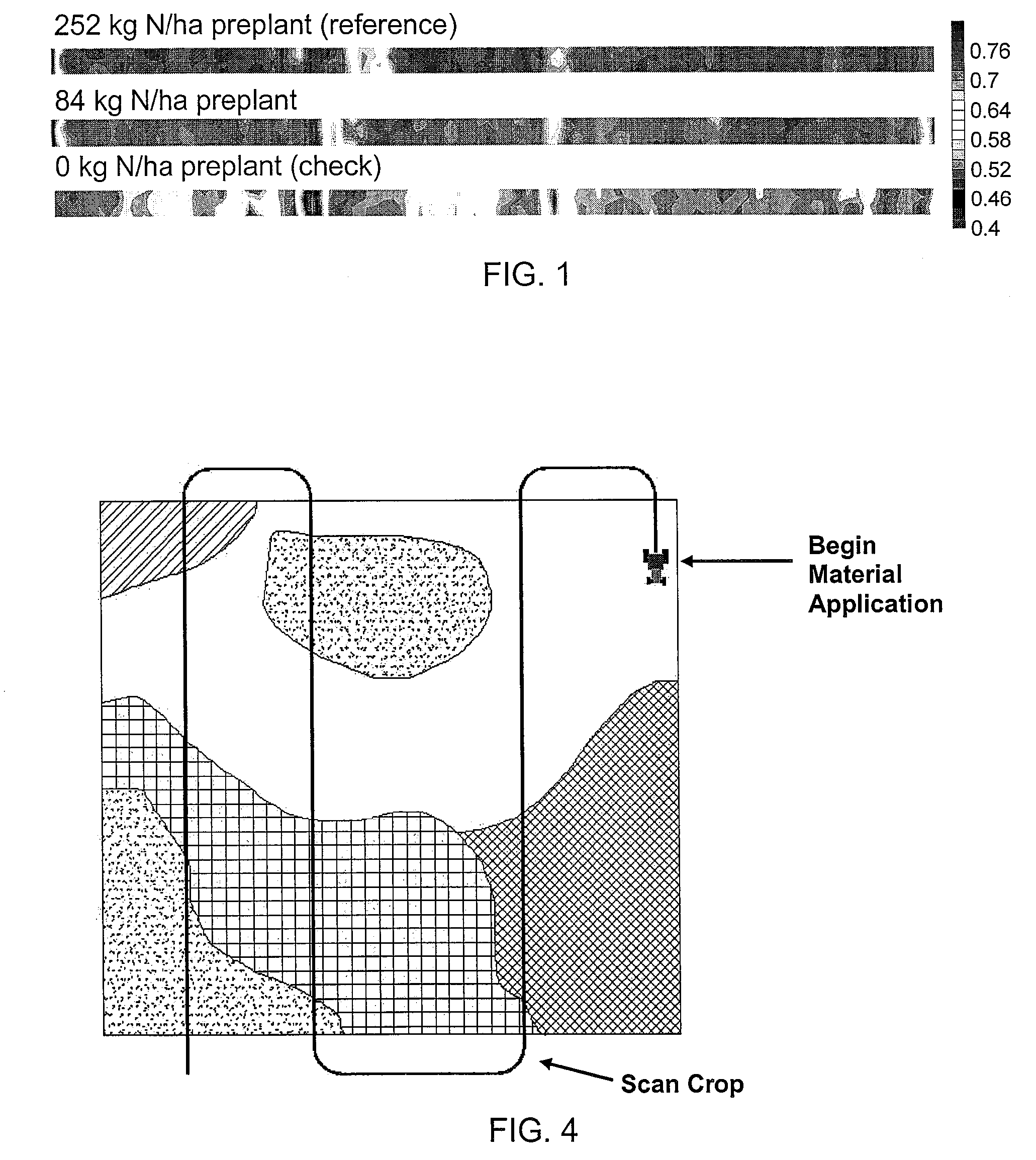
[0037]A grower decides to variably apply nitrogen to a field. He decides to apply 100 kg / ha on average and that his maximum and minimum rates should be 50 and 150 kg / ha, respectively. These parameters are loaded into the variable rate controller located inside his tractor. Next, the grower drives several transect through his field to collect crop growth information, see FIG. 4. Note, the coefficients in equation (1) become: SApp equal 100 kg / ha, G equal 50 kg / ha, k equal 1.0 and for simplicity function ƒ(α) is the function argument α, equation (2), (normally ƒ(α) would be a curvilinear function that would characterize the growth behavior of the crop). The parameters for the variable α are determined via the transects through the field and will be bounded so as to produce a range of values between −0.5 and 0.5 around the field average. Equation (1) is now has the following form:

SRate=100+50·α  (6)

[0038]He then proceeds to drive the field and apply nitrogen to his crop. At the sensing...

example 2

[0039]Now consider the previous example but this time allowance for real-time zone factor adjustment of the application rate is performed with the use of a soil sensor 50 in FIG. 5. The VRA system is driven through the as was done in example 1 above in order to collect crop biomass information, see FIG. 6. After the crop data has been collected, VRA system changes to the application mode to apply material to the crop. Material application is now based on both crop sensor readings and soil sensor readings. In this example the soil sensor 50 is a reflectance sensor that produces an NDVI output that is proportional to soil color. The output of the soil sensor is fed into a look up table that will be used to generate values for the zone factor k. A typical look-up table may take on the form as shown in Table 2.

[0040]

TABLE 2Real-time zone factor look-up table based on soil NDVI measurements.Soil NDVIZone Factor, k0 1.00.3 0.870.35 0.750.385 0.5NDVI > 0.410.25

[0041]A similar table can be ...


PUM


Abstract

An algorithmic method is described for sensor-based real-time application of an agricultural material. Method includes means for characterizing and treating crop biomass variability without the use of a grower managed reference crop. Crop variability is determined statistically by driving one or more transects through the field in order to collect crop canopy information for sensor calibration purposes.

Description

[0001]This application claims priority to U.S. Patent Application Ser. No. 60 / 958,330, filed Jul. 3, 2007.BACKGROUND OF THE INVENTION[0002]1. Field of the Invention[0003]This invention relates generally to crop canopy light sensors and, more specifically, to an algorithm and method for the real-time application of agrochemicals utilizing active crop-canopy light sensors.[0004]2. Background of the Art[0005]The term “precision farming” is often used to describe the management of spatial variability in soil and crop conditions within a field. Other terms, “site specific farming”, “prescription farming”, and “variable rate application (VRA) technology” are sometimes used synonymously with precision farming to describe the tailoring of soil and crop management to the conditions at various locations throughout a field. Typical precision farming techniques include: varying the planting density of individual plants based on the ability of the soil to support growth of the plants; and the se...

Claims


Application Information

Patent Timeline
Patent Type & Authority Patents(United States)
IPC IPC(8): G01C21/02G01C21/24
CPCA01C21/007A01B79/005
Inventor HOLLAND, KYLE
Owner KYLE H HOLLAND TRUSTEE OF THE MARANATHA TRUST DATED JULY 30 2013
Why Eureka
Try Eureka