
Condensation particle counter

a technology of condensation particle and counter, which is applied in the direction of packaging foodstuffs, instruments, packaged goods, etc., can solve the problems of organic compound that is detrimental to the human body, gives off a strong smell, and cannot detect fine particles by optical particle counters,

Active Publication Date: 2010-05-25
HCTM +1
View PDF7 Cites 9 Cited by
  • Summary
  • Abstract
  • Description
  • Claims
  • Application Information

AI Technical Summary

Benefits of technology

Enables efficient and accurate measurement of fine particles using water as the working fluid, improving particle detection and reducing the need for multiple counters and frequent replacements, while ensuring reliable data and safer operation.

Problems solved by technology

This poses a problem in that the fine particles cannot be detected by means of the optical particle counter.
The organic compound is detrimental to the human body and gives off a strong smell.
In addition, the organic compound is highly difficult to handle because it is flammable.
Particularly, if an alcohol-based organic material is used as the working fluid of the condensation particle counter in a semiconductor manufacturing process, the organic material acts as a pollutant and therefore becomes a cause of defect.
Inasmuch as the organic compound tends to absorb moisture contained in a gas, the condensation particle counter suffers from degradation in performance if the organic compound is used for a long period of time.
Therefore, several condensation particle counters have to be used in combination in order to measure a large quantity of aerosol in one place, which is cumbersome and inconvenient.
Furthermore, in case of using several condensation particle counters at one time, it is very difficult to uniformly control the temperature of the saturator and the condenser of the individual condensation particle counters.
If a great deviation exists in the temperature of the saturator and the condenser, the data obtained by measuring the fine particles become less reliable.

Method used


Image

  • Condensation particle counter
  • Condensation particle counter
  • Condensation particle counter

Examples


Embodiment Construction

[0021]A preferred embodiment of a condensation particle counter in accordance with the present invention will now be described in detail with reference to the accompanying drawings.

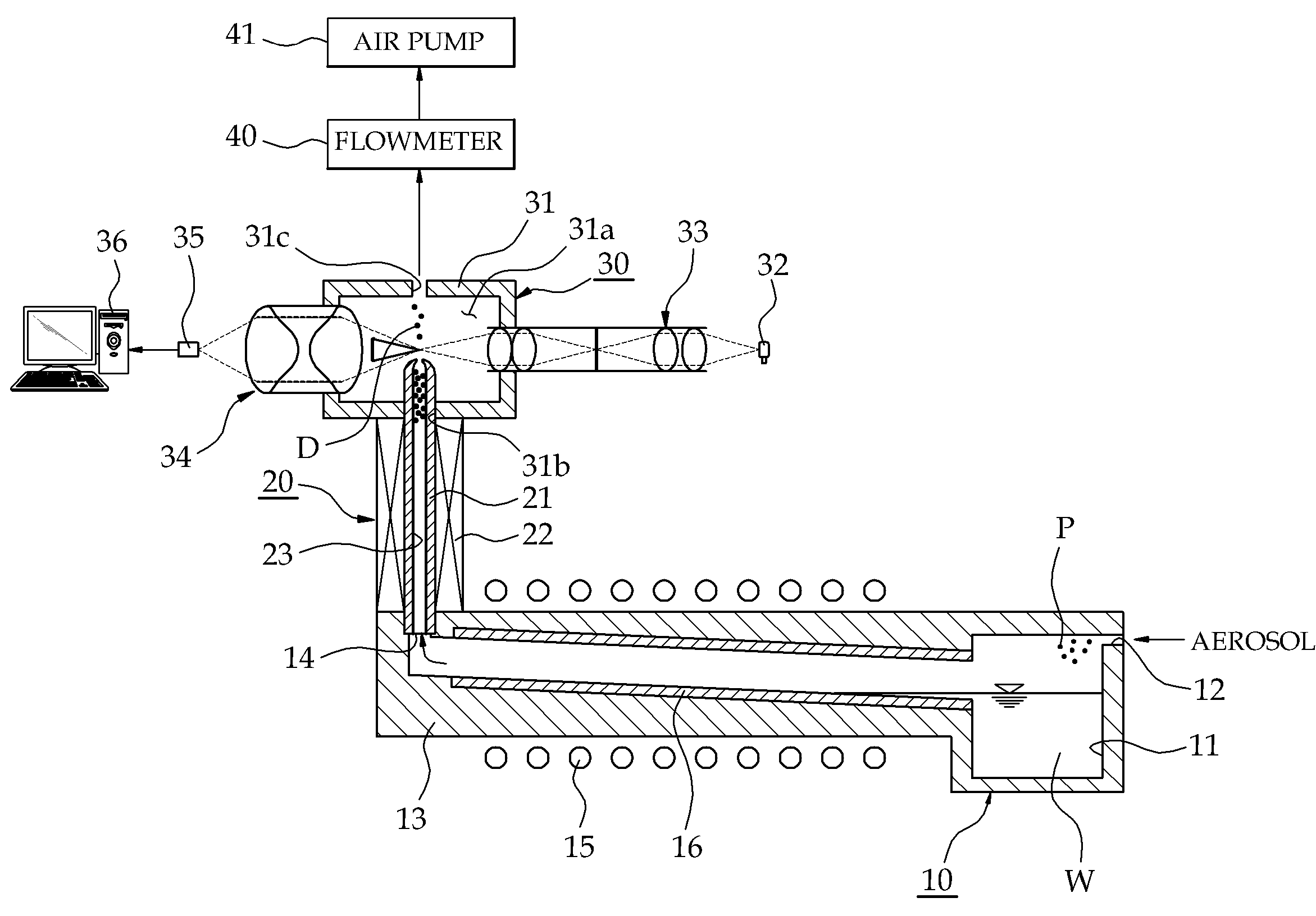
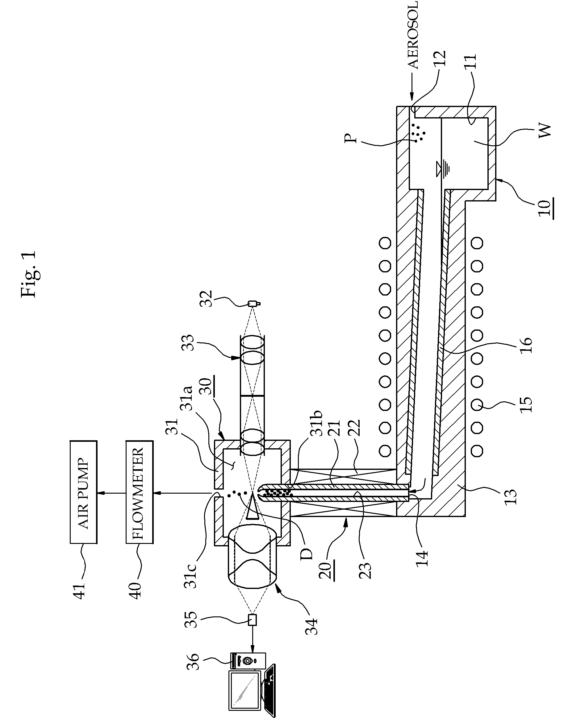
[0022]Referring first to FIG. 1, a condensation particle counter of the present invention includes a saturator 10 for generating a saturated gas by allowing working fluid to saturate a gas in which fine particles P is suspended, a condenser 20 for condensing the saturated gas and an optical particle counter 30 for optically detecting the fine particles P to calculate the number and size of the fine particles P.

[0023]The saturator 10 is provided with a pool 11 that contains working fluid W. The pool 11 is connected to an inlet port 12 of the saturator 10 through which an aerosol, i.e., a gas in which fine particles P are suspended, is introduced. A saturator tube 13 for guiding the stream of the saturated gas is connected to one side of the pool 11. The saturator tube 13 has an outlet port 14 through which...


PUM

PropertyMeasurementUnit
temperatureaaaaaaaaaa

Abstract

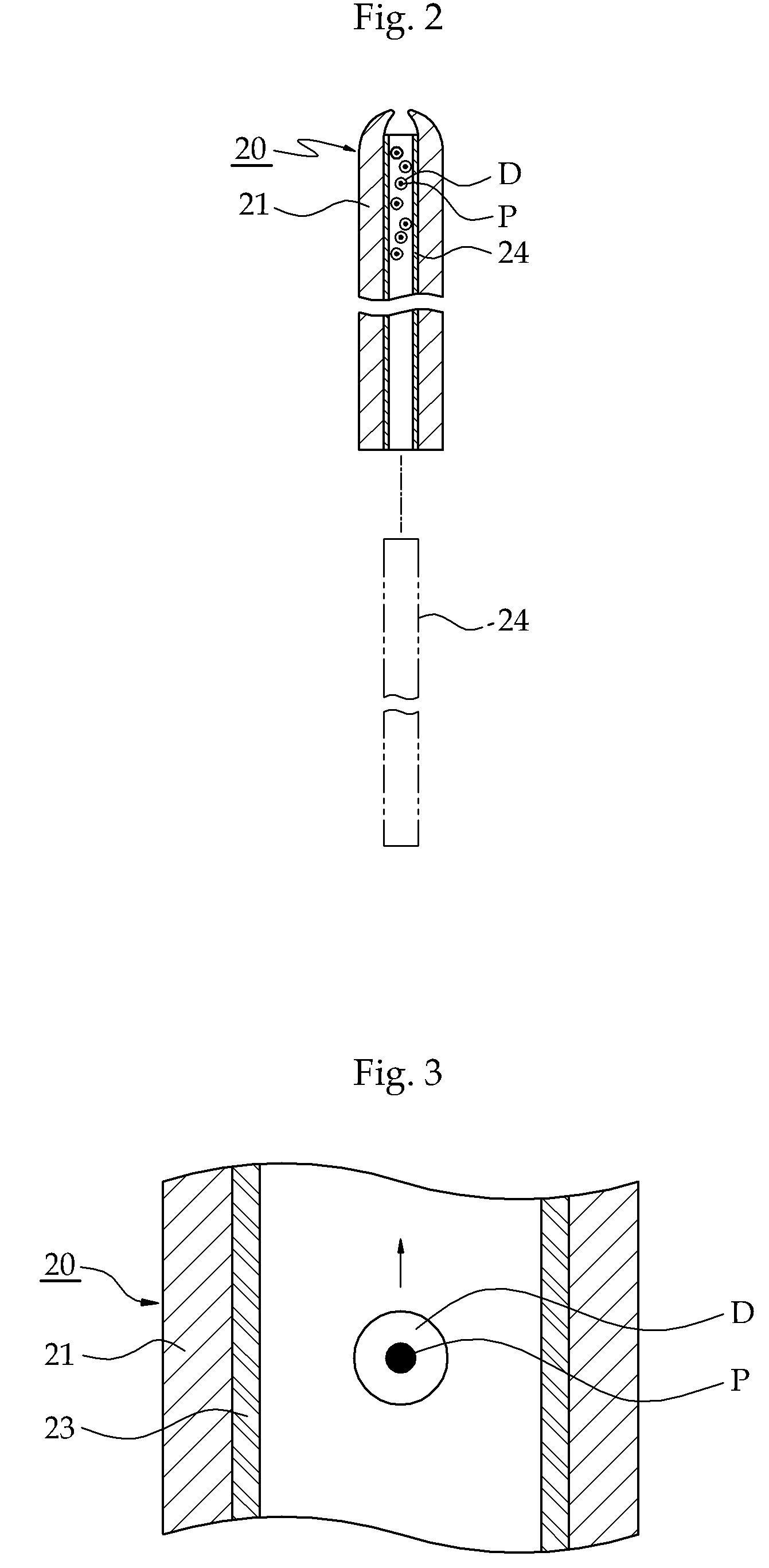
A condensation particle counter is capable of efficiently measuring the number and size of fine particles. The condensation particle counter includes a saturator, a condenser and an optical particle counters. The saturator is designed to generate a saturated gas by saturating a gas in which fine particles are suspended with working fluid. The condenser is connected to a downstream side of the saturator to condense the saturated gas so that liquid droplets can grow around the fine particles. The optical particle counter is connected to downstream sides of the condenser to optically detect the liquid droplets supplied from the condensers. The condenser has a condenser tube for interconnecting the saturator and the optical particle counter. The present condensation particle counter can use water as working fluid and also can optically measure fine particles in an easy and accurate manner by forming or installing an inner surface of a condenser tube with a hydrophilic tube.

Description

RELATED APPLICATION[0001]The present application is based on, and claims priority from, Korea Application Number 10-2007-0067518, filed Jul. 5, 2007, the disclosure of which is hereby incorporated by reference herein in its entirety.FIELD OF THE INVENTION[0002]The present invention relates to a condensation particle counter. Especially, the present invention relates to a condensation particle counter using water as a working fluid for efficiently measuring the number and size of fine particles.BACKGROUND OF THE INVENTION[0003]A condensation particle counter comprises a saturator, a condenser and an optical particle counter (OPC) and is widely used in measuring the number and size of fine particles. The saturator of the condensation particle counter contains working fluid to saturate an aerosol, i.e., a particle-suspended gas. Examples of the working fluid include alcohol-based fluid such as alcohol, butanol, isopropyl alcohol or the like and organic compound fluid such as ethylene g...

Claims


Application Information

Patent Timeline
Patent Type & Authority Patents(United States)
IPC IPC(8): G01N15/02
CPCG01N15/065G01R33/563A61J1/22
Inventor AHN
Owner HCTM
Learn More