Circuit device

a circuit device and circuit technology, applied in the direction of fixed capacitor details, printed circuit non-printed electric components association, lighting and heating apparatus, etc., can solve the problems of reducing disadvantageous reduction of the reliability of the circuit device, and achieve the effect of suppressing the reduction of reliability

Inactive Publication Date: 2010-05-25
SANYO ELECTRIC CO LTD
View PDF8 Cites 3 Cited by
  • Summary
  • Abstract
  • Description
  • Claims
  • Application Information

AI Technical Summary

Benefits of technology

[0010]The present invention has been proposed in order to solve the aforementioned problems, and an object of the present invention is to provide a circuit device capable of suppressing reduction of reliability resulting from heat generated in a circuit element.

Problems solved by technology

Thus, reliability of the circuit device is disadvantageously reduced.
This may result in defective connection of the wire of the circuit device, to also reduce the reliability of the circuit device.

Method used


Image

  • Circuit device
  • Circuit device
  • Circuit device

Examples


Embodiment Construction

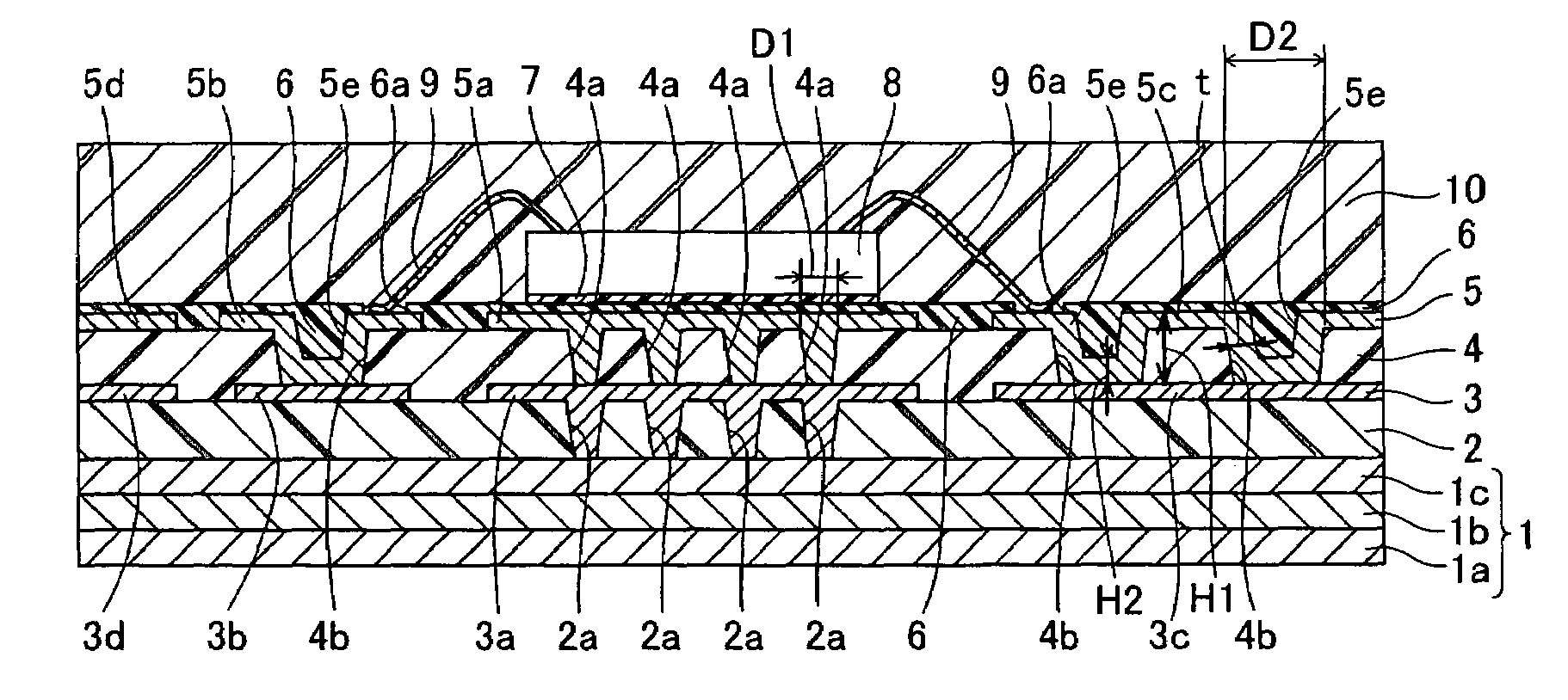
[0039]An embodiment of the present invention is now described with reference to the drawings.

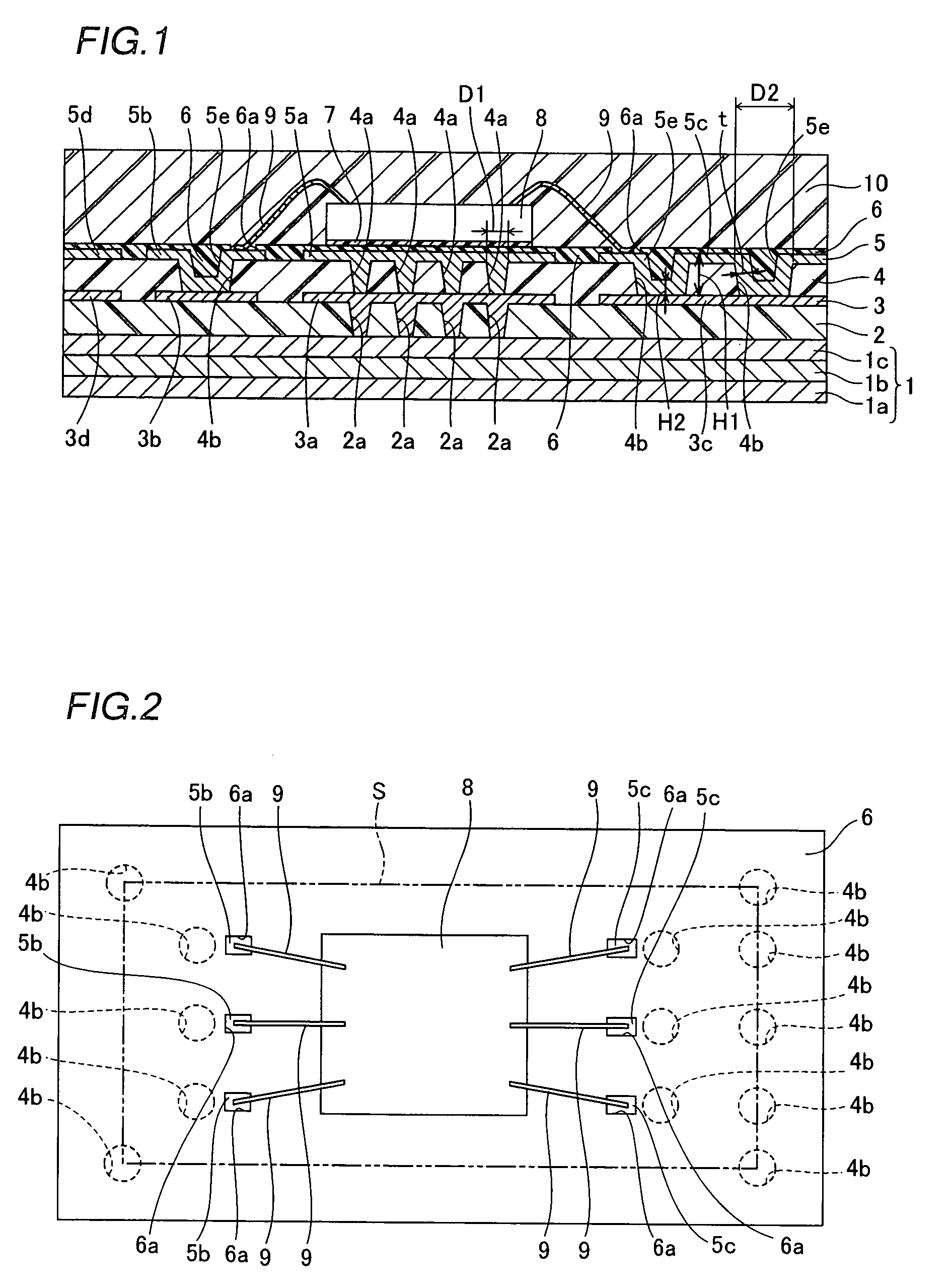
[0040]The structure of a circuit device according to this embodiment is described with reference to FIGS. 1 and 2.

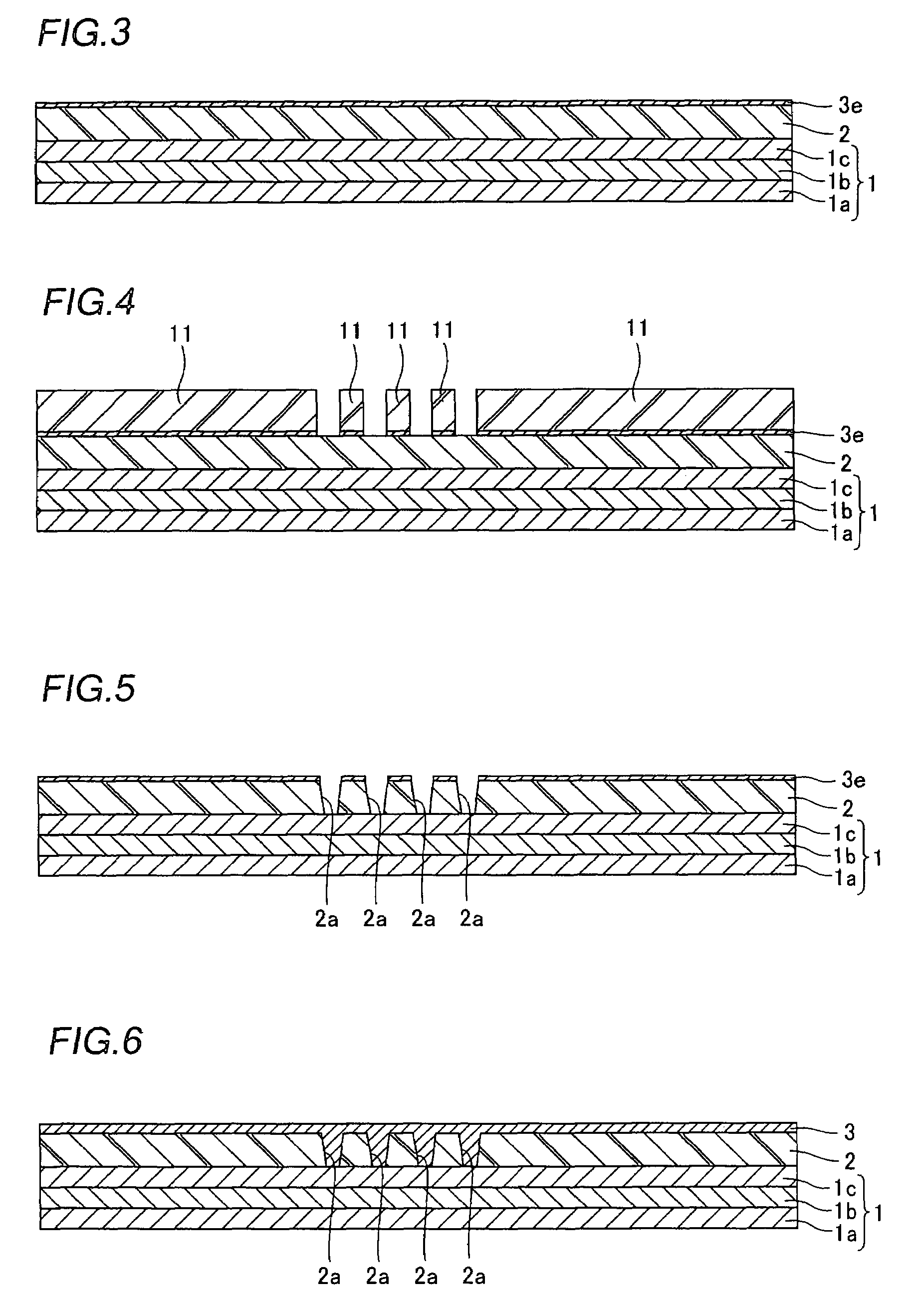
[0041]In the circuit device according to this embodiment, a substrate 1 having a thickness of about 100 μm to about 3 mm (about 1.5 mm, for example) is employed as shown in FIG. 1. This substrate 1 is constituted of a clad material prepared by stacking a lower metal layer 1a of copper, an intermediate metal layer 1b of an Fe—Ni alloy (the so-called invar alloy) formed on the lower metal layer 1a and an upper metal layer 1c of copper formed on the intermediate metal layer 1b. The substrate 1 is an example of the “metal substrate” in the present invention.

[0042]A first insulating layer 2, mainly composed of epoxy resin, having a thickness of about 60 μm to about 160 μm is formed on the surface of the substrate 1. This insulating layer 2 is an example of the “second insulating layer...


PUM


Abstract

A circuit device capable of suppressing reduction of reliability resulting from heat generated in a circuit element is obtained. This circuit device comprises a first insulating layer having a first opening and a second opening, a first conductor filling up the first opening of the first insulating layer, a second conductor, formed along the inner side surface of the second opening of the first insulating layer, having a concave upper surface and a circuit element arranged above a region of the first insulating layer formed with the first opening.

Description

BACKGROUND OF THE INVENTION[0001]1. Field of the Invention[0002]The present invention relates to a circuit device, and more particularly, it relates to a circuit device comprising a circuit element.[0003]2. Description of the Background Art[0004]In a circuit device included in an electronic apparatus or the like, the heating value per unit volume has recently been increased due to downsizing, densification and multi-functioning. In recent years, therefore, a metal substrate having high heat radiability has been employed as the substrate for the circuit device, and a circuit element such as an IC (integrated circuit) or an LSI (large-scale integrated circuit) has been mounted on the metal substrate (refer to Japanese Patent Laying-Open No. 7-193347 (1995), for example).[0005]FIG. 16 is a sectional view showing the structure of a conventional circuit device disclosed in the aforementioned Japanese Patent Laying-Open No. 7-193347. Referring to FIG. 16, a wiring structure 102 is formed ...

Claims


Application Information

Patent Timeline
Patent Type & Authority Patents(United States)
IPC IPC(8): H05K1/18
CPCH01L23/3677H01L23/49827H05K1/0206H05K3/421H01L24/45H05K1/114H05K3/28H05K3/4644H05K2201/094H05K2201/09509H05K2201/09563H05K2201/096H05K2203/049H01L24/48H01L2224/32225H01L2224/48227H01L2224/73265H01L23/49822H01L2224/451H01L2924/00H01L2924/00012H01L2924/00014H01L24/73H01L2924/14H01L2924/181
Inventor USUI, RYOSUKEMIZUHARA, HIDEKIINOUE, YASUNORIKOBAYASHI, KATSUNORI
Owner SANYO ELECTRIC CO LTD
Why Eureka
Try Eureka