Optical heterodyne sampling device having probe and pump beams

a sampling device and heterodyne technology, applied in the field of ultra high-speed, non-destructive measurement, can solve the problems of limiting temporal resolution and no longer fixed delay t/sub>ps/sub>between the pump and the probe pulse train, and achieve the effects of reducing temporal resolution, limiting temporal resolution, and long acquisition tim

Active Publication Date: 2010-06-01
CENT NAT DE LA RECHERCHE SCI
View PDF3 Cites 9 Cited by
  • Summary
  • Abstract
  • Description
  • Claims
  • Application Information

AI Technical Summary

Benefits of technology

[0012]This technique allows the sample reaction to be measured without mechanical translation and thus without alteration of the beam focus point on the sample.
[0013]The delay Tp−Ts does not actually vary linearly, as the frequencies Fp and Fs vary at random because of the natural jitter of the lasers. This jitter has the effect of randomly modulating the beat frequency ΔF by a quantity g(t). This phenomenon is even more significant if it is desired that a reduced temporal resolution be obtained. In fact, for a period Tp of 13 ns, 13,000 measurements are required to achieve a temporal resolution of 1 ps, since the uncertainty introduced by the jitter for each measurement accumulates over time. The jitter thus has the effect of limiting the temporal resolution.
[0014]The object of the invention is to allow measurements with a temporal resolution of approximately 1 ps or less (100 fs) to be obtained, without the need to carry out mechanical translation and without being disadvantaged either by a very long acquisition time or by the jitter.

Problems solved by technology

The delay Tps between the pump and probe pulse trains is no longer fixed, as in the case of homodyne sampling, but changes over time.
The jitter thus has the effect of limiting the temporal resolution.

Method used


Image

  • Optical heterodyne sampling device having probe and pump beams
  • Optical heterodyne sampling device having probe and pump beams
  • Optical heterodyne sampling device having probe and pump beams

Examples


first embodiment

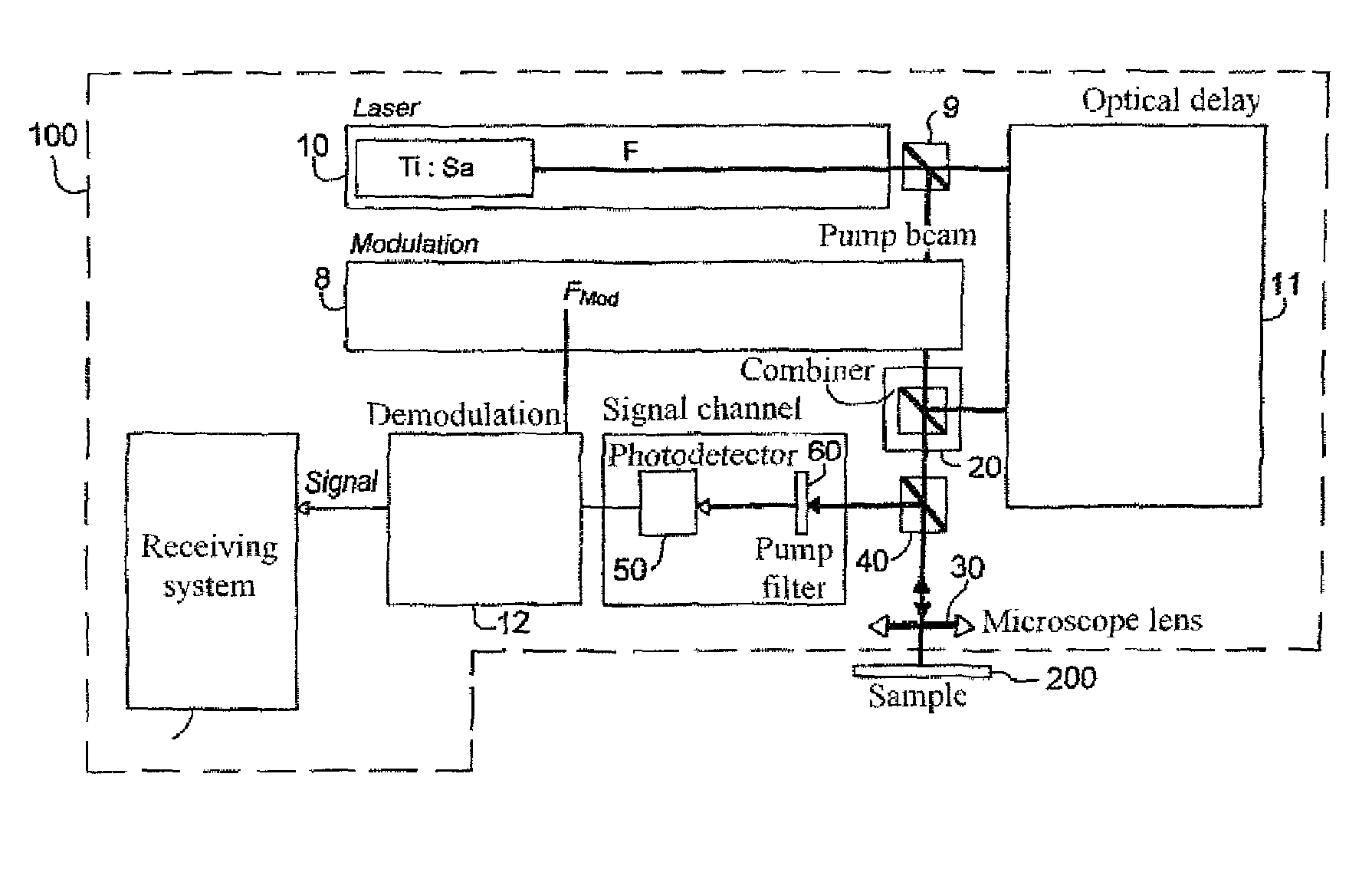
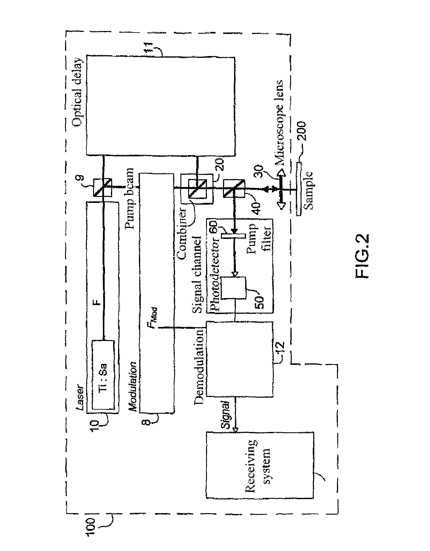
[0092] described with reference to FIGS. 6a and 7a, the scanning device 300 is included in the combiner 20, for example upstream from the semi-transparent slide 22; the beams are combined by the combiner 20 but are not superimposed. The probe beam scans the sample 200 whilst the pump beam remains in a fixed position on the sample.

second embodiment

[0093] described with reference to FIGS. 8a and 9a, the scanning device 300 is downstream from the combiner 20; the pump and probe beams are combined and superimposed by the combiner 20 and are superimposed on the sample 200.

[0094]In the above embodiments, the pump and / or probe beams are displaced, the sample 200 being fixed.

[0095]According to a further embodiment, described with reference to FIGS. 10a and 10b, the pump and probe beams are fixed and the scanning device 300 is thus a translation plate in the plane of the sample, on which plate the sample 200 is mounted.

[0096]The pump and probe beams shown in FIGS. 6 to 10 may be swapped around.


PUM


Abstract

An optical heterodyne sampling device includes: two pulsed laser sources which may have a jitter and which can receive respectively a pump beam and a probe beam having respective repetition frequencies Fs and Fp, whereby Fs≠Fp; and an element for combining the pump beam and the probe beam which are intended to be passed over a sample, consisting of a signal channel including a system for the photodetection of the response signal from the sample and a system for acquiring the photodetected signal, which is connected to the signal channel. According to the invention, Fs and Fp are essentially constant and the acquisition system includes an acquisition trigger element. A synchronization channel is connected to the trigger element, and includes a device for measuring the beat frequency |Fs−Fp| which can generate a synchronization signal comprising pulses each time the pulses of the pump beam and the probe beam coincide.

Description

BACKGROUND OF THE INVENTION[0001]1. Field of the Invention[0002]The field of the invention is the ultra high-speed, non-destructive measurement of the mechanical, thermal or optical properties of a material. Ultra High-speed measurement is understood to mean a measurement with a temporal resolution of the order of a picosecond.[0003]2. Description of the Related Art[0004]It is known to obtain measurements with a temporal resolution of this type via optical sampling techniques using two pulse trains respectively designated “pump” and “probe” trains, with pulse period T, each pulse having a duration τ of approximately 100 femtoseconds.[0005]The pump beam causes a disturbance in the material or sample which in response produces an optical signal dependent on the optical properties thereof (reflectivity, absorption, expansion, contraction etc.). The probe beam is delayed by a quantity Tps referred to as the “pump-probe” delay and reads the reaction of the material; it is generally of a ...

Claims


Application Information

Patent Timeline
Patent Type & Authority Patents(United States)
IPC IPC(8): H01J40/14G01Q60/22
CPCG01J11/00G01N21/17G04F13/026G01J9/04H01S3/1394G01N2021/1791G01N2021/1736
Inventor DILHAIRE, STEFANCLAEYS, WILFRIDRAMPNOUX, JEAN-MICHELROSSIGNOL, CLEMENT
Owner CENT NAT DE LA RECHERCHE SCI
Why Eureka
Try Eureka