Transmission line notch filter

a technology of transponder and notch filter, which is applied in the structural form of radiating elements, waveguide devices, resonance antennas, etc., can solve the problems of damage being known to look like esd, reports of tag failures began to surface, damage was thought to be caused, etc., and achieves no more risk

Active Publication Date: 2010-06-01
AMTECH SYST
View PDF11 Cites 4 Cited by
  • Summary
  • Abstract
  • Description
  • Claims
  • Application Information

AI Technical Summary

Benefits of technology

[0017]The known limiter diode and the band pass filters have added the cost to the final RFID product, while the notch filter would provides the same or better filtering with no more risk than the limiter or discrete component filters without adding the cost, because the notch filter comes with the printed circuit.

Problems solved by technology

Early in 1992, reports of tag failures began to surface.
Initially, the damage was thought to be caused by electrostatic discharge (ESD) damage during tag programming.
The damage was known to look like ESD, affecting the sensitive diodes on the tag antenna used to convert RF (radio frequency) signals to DC (direct current) power.
The effectiveness of the technical solution and the design of the tags are proven by over 15 years of operation of these tags in the harsh rail environment without problems, however, the implementations have added significantly to the cost of the tag.
In particular, the use of limiter diodes and discrete band filters adds a considerable cost increase of $0.50 and $0.20, respectively per tag, which is significant considering the large product volume.

Method used


Image

  • Transmission line notch filter
  • Transmission line notch filter
  • Transmission line notch filter

Examples


Embodiment Construction

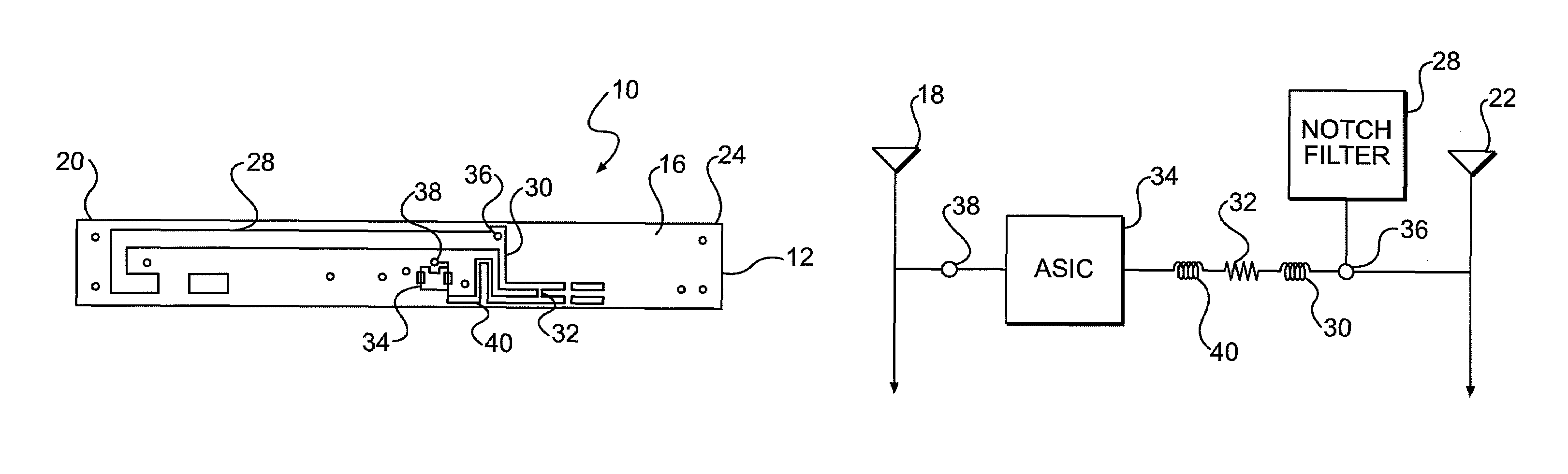
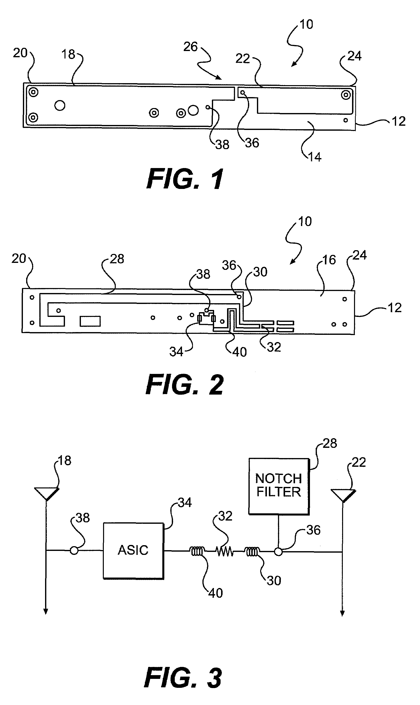
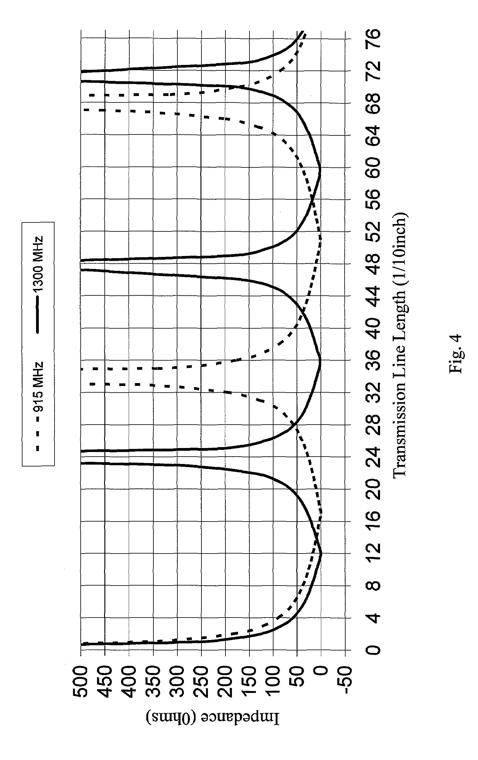
[0025]The most common transmission line filters use a ¼ wavelength transmission open or short stub that transforms an open circuit to a short or a short circuit to an open, respectively. The transmission line for this invention strays from conventional approaches by using a transmission line length determined such that the filter impedance is very high at the operating frequency range and very low at the stop frequency range in comparison to the operating impedance. Therefore the pass-band and stop-band frequencies determine the transmission line length rather than conventionally used quarter wavelength transmission lines. For example, the preferred transmission line length for the exemplary notch filter disclosed herein is about 3.4 to 3.5 inches instead of the conventional 1.7 inch ¼ wavelength transmission line length for a 915 MHz signal.

[0026]To suppress the 1300 MHz signal, a junction between the antenna and the antenna impedance matching circuit is used to connect the shunt n...


PUM

PropertyMeasurementUnit
impedanceaaaaaaaaaa
impedanceaaaaaaaaaa
lengthaaaaaaaaaa

Abstract

A transponder includes a notch filter to suppress the 1300 MHz at minimal product cost increase. The notch filter utilizes a printed transmission line length adjusted to a correct length. This notch filter will connect to the antenna matching circuit at a junction between the antenna and an ASIC as a shunt component with high impedance (e.g., greater than 500 Ohms) at 915 MHz and low impedance (e.g., less than 10 Ohms) at 1300 MHz. Since the operating impedance of the junction is about 200 ohms, the 915 MHz signal from the antenna will feed the ASIC without any attenuation with a high shunt impedance component, while the 1300 MHz signal will be attenuated significantly by a low shunt impedance component. The transponder is applicable for all types of RFID tags (e.g., passive, semi-passive, active, read only, read-write, read first, tag-talk first) and is well suited for tags operating at radio frequencies, including microwave frequencies (e.g., 902 MHz to 928 MHz) in the U.S.

Description

BACKGROUND OF THE INVENTION[0001]1. Field of the Invention[0002]This invention relates to an antenna system in a transponder for modulating signals from a reader and for reflecting the modulated signals back to the reader to pass information from the transponder to the reader.[0003]2. Description of Related Art[0004]RFID (radio frequency identification) tags have been used for highway toll collections, tracking railroad freight cars, parking access, and inventory controls. These RFID tags typically consist of an antenna, an antenna impedance matching circuit, and an Application Specific Integrated Circuit (ASIC). The antenna receives the RF signals from the interrogator (reader), and feeds the signal to the ASIC through the antenna matching circuit between the antenna and ASIC. ASIC has hardware and software circuits to handle the RF signals and the signal processing respectively.[0005]In the early 1990s, passive Radio Frequency Identification (RFID) systems were selected by the Ass...

Claims


Application Information

Patent Timeline
Patent Type & Authority Patents(United States)
IPC IPC(8): H01Q1/36H01Q1/50
CPCH01P1/203H01P1/20336Y10T29/49016
Inventor YOUN, TAI WON
Owner AMTECH SYST
Why Eureka
Try Eureka