Motion compensated light-emitting apparatus

a light-emitting apparatus and motion-recognition technology, applied in the direction of optical radiation measurement, instruments for comonautical navigation, instruments, etc., can solve the problems of unintentional angular and/or translation, unsteady light column, and affect the conventional light-emitting device, etc., to achieve low power consumption and vibration stability, high output, and high mobility

Active Publication Date: 2010-06-01
FEINSOD MATTHEW +1
View PDF27 Cites 6 Cited by
  • Summary
  • Abstract
  • Description
  • Claims
  • Application Information

AI Technical Summary

Benefits of technology

[0008]In an alternate embodiment of the present invention a motion compensated, light-emitting device is provided that displays a variety of stabilized-rasterized and stabilized-vector graphics as well as stabilized multi-frame animations at arbitrary refresh rates. The system is highly adaptable to projection onto various surfaces and in a variety of applications, including projection onto specially-coated transparent surfaces. Due to the low power consumption and vibration stabilized output of this device, the system preferably is miniaturized, highly portable and fully mobile when used with a laptop small computer. The computer may project different letters, symbols, or graphics or other static or moving images that can change and evolve over time. The system preferably includes a two axis MEMS micro mirror. The signals providing the desired rasterized or vector graphics are added to the vibration stabilization signals, and unwanted movement is reduced or eliminated in the resulting projection.
[0009]In an alternate embodiment of the present invention, a motion-compensated, light-emitting device displays full color, high-quality images that remain in focus at all distances using holographic laser projection technology. The term “holographic” refers not to the projected image, but to the method of projection. A diffraction pattern of the desired 2D image, calculated using holographic algorithms, is displayed on a phase-modulating Liquid Crystal on Silicon (LCOS) microdisplay attached to a two axis MEMS micro mirror. When illuminated by coherent laser light, the desired image is projected on various surfaces without distortion by the micro-tremors imposed on the projection system.
[0010]Rather than blocking light, a phase-modulating LCOS microdisplay mounted on the MEMS micro mirror steers light to exactly where it is needed, making the system highly efficient. Unlike conventional projection systems, a projection lens is not needed. Instead, a demagnification lens pair expands the diffracted image from the microdisplay, producing an ultra-wide throw angle, greater than 100°. The projected images are in focus at all distances from the projector, eliminating the need for focus control.
[0011]The diffractive method of projection naturally lends itself to miniaturization and low cost implementation, allowing images to be projected onto curved and angled surfaces without distortion. In addition, the system is highly tolerant of microdisplay pixel failure—essential in safety critical applications in markets such as automotive.
[0012]In an alternate embodiment of the present invention a motion-compensated, light-emitting device stores the exact orientation of the laser or projection system for later retrieval, derived from a location determination system, a range to target determination system and information from motion detection devices such as accelerometers under user control. The system automatically maintains a light beam emitted from the device in the exact orientation, as stored. In addition, the system may store several orientations, and the system can reorient the light beam in sequential, round-robin fashion. With sufficient displacement of the compensating mirrors, the system can be moved from its location, and if the targets are far enough away, the system can maintain the orientation of the light beam at the marked targets. In addition, by adding some simple modulation to the laser light beams the beams can be turned off when not actually pointing at memorized locations, thus maintaining illumination only at the desired locations that were previously set in memory.

Problems solved by technology

However, conventional light-emitting devices may be affected by unintentional angular and / or translational movements (e.g., fine vibrations from the machine in which a laser is encased, fine tremors from a shaking hand holding a laser, etc.) and, as a result, generate an unsteady column of light—producing an effect that may cause inferior performance.
These unwanted vibrations are often amplified when the person maneuvering the device is nervous.

Method used


Image

  • Motion compensated light-emitting apparatus
  • Motion compensated light-emitting apparatus
  • Motion compensated light-emitting apparatus

Examples


Embodiment Construction

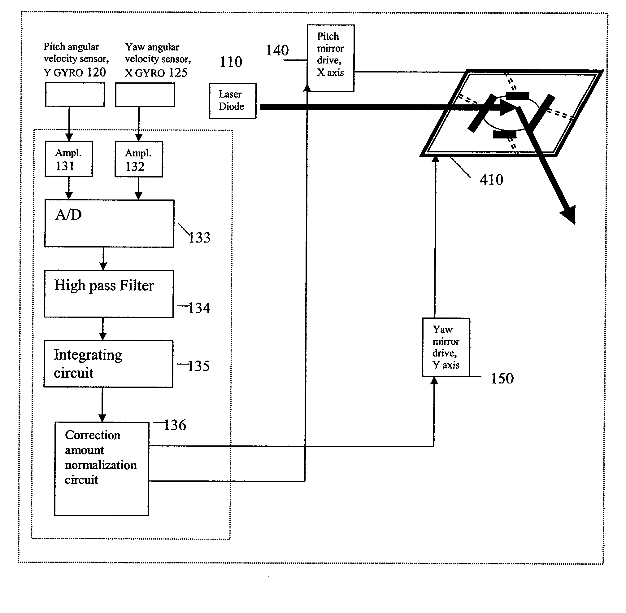
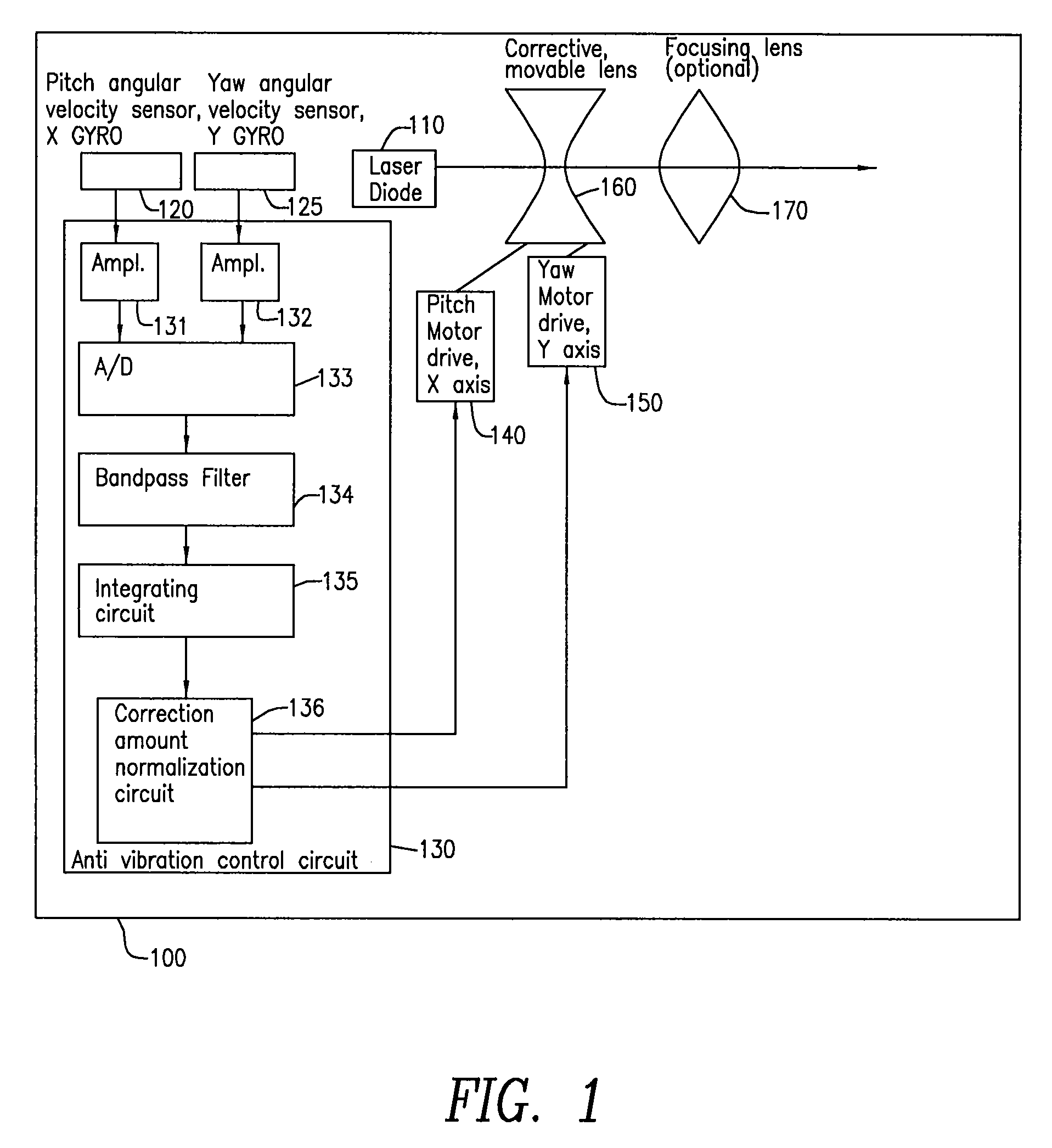
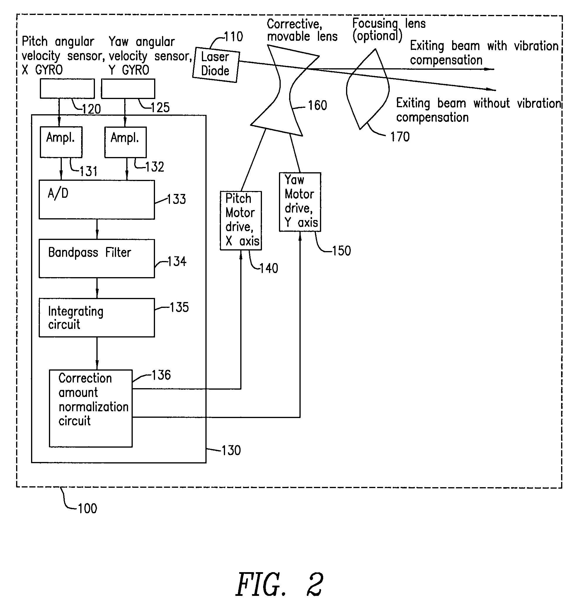
[0046]FIG. 1 is a diagram of a laser diode pointer 100 which includes vibration or motion compensation circuitry in accordance with an embodiment of the invention. A visible laser diode 110 may be used as the light source. There are several ways of implementing the vibration compensation scheme. In accordance with an embodiment of the invention, two angular velocity sensors (gyros) 120 and 125 are aligned in orthogonal directions and used to measure the angular movements in the pitch and yaw axis (also referred to as the X and Y axis). In a preferred embodiment, the two miniature gyroscopes comprise, for example, a micro electro mechanical system (“MEMS”), such as model ADXRS150 manufactured by Analog Devices, Inc. These gyros may have a relatively small volume (such as less than 0.15 cm3), low weight (such as less than 500 mg), and small size (such as 7 mm×7 mm×3 mm or less). In another embodiment of the present invention, a motion-compensating light-emitting device is provided whi...


PUM


Abstract

A light-emitting apparatus, for enabling a beam of light to be projected on a desired target located a distance away to project the beam on the desired target without any or substantially any undesired movement. The apparatus may include a housing, a light generating device located within the housing and operable to generate a beam of light, a sensing device or devices for sensing an undesired action of the housing, a control circuit operable to provide a control signal corresponding to the sensed undesired action, and a drive device operable to counter act all or at least some of the undesired action of said housing in accordance with said control signal. The sensing device or devices may be one or more gyroscopes, accelerometers or other such devices.

Description

CROSS REFERENCE TO RELATED APPLICATIONS[0001]This application is a continuation-in-part of U.S. patent application Ser. No. 11 / 315,906, filed Dec. 22, 2005, entitled Motion-Compensating Light-Emitting Apparatus, which in turn is a continuation-in-part of U.S. patent application Ser. No. 11 / 022,215, now U.S. Pat. No. 7,312,863, filed Dec. 23, 2004, entitled Motion-Compensating Light-Emitting Apparatus, all of which are incorporated by reference herein.FIELD OF THE INVENTION[0002]The present invention relates generally to a system for maintaining a beam of electromagnetic radiation, such as visible light, pointed in a particular direction, despite unwanted movement of the device emitting the beam with respect to an inertial frame of reference.BACKGROUND OF THE INVENTION[0003]The present invention relates to light-emitting devices and particularly to those devices intended to produce a beam in a selected direction such as toward a target of interest. The invention provides motion-compe...

Claims


Application Information

Patent Timeline
Patent Type & Authority Patents(United States)
IPC IPC(8): G01C1/10G01C21/02G01C21/24G01J1/20
CPCG02B27/20G02B27/646G02B26/08H01S5/0071H01S5/005
Inventor FEINSOD, MATTHEWPERLMUTTER, MICHAEL
Owner FEINSOD MATTHEW
Why Eureka
Try Eureka