3-d optical microscope

a three-dimensional, optical microscope technology, applied in the field of optical microscopes, can solve the problems of inability to quantitatively measure the depth dimension, difficult to maintain and operate, and expensive construction of conventional microscopes, and achieve the effect of reliable and accurate 3-d imaging and low cos

Active Publication Date: 2010-06-01
KLA CORP
View PDF11 Cites 50 Cited by
  • Summary
  • Abstract
  • Description
  • Claims
  • Application Information

AI Technical Summary

Benefits of technology

[0008]The need is met with the present invention which achieves three objectives: first, to create a simple and relatively low cost microscope that is capable of generating a 3-D image on samples with or without contrast; second, to propose simple hardware modifications that one can make to turn a conventional optical microscope into a 3-D optical microscope; and third, to disclose a method that enables reliable and accurate 3-D imaging on almost any sample regardless of its image contrast.

Problems solved by technology

A conventional microscope, however, has important limitations.
Although Costales' microscope produces a perception of depth, it cannot provide quantitative measurement of the depth dimension.
Although a confocal microscope is able to generate a 3-D image and provide quantitative depth measurement, it is expensive to build and relatively complex to maintain and operate.
In addition, if one already bought a conventional microscope, it is not easy and in many cases impossible to turned his microscope into a confocal microscope.
Although it is cost effective to implement such a method, it only works on samples with contrasting features.
In short, Sieckmann's method fails to generate a reliable and accurate 3-D image of a sample with little or no contrast.
As a result, his sensor does not yield a 3-D image.
In addition, the pattern of light in Morgan's sensor is always superimposed on the sample surface, and thus interferes with the true features of the sample surface being captured by a camera.

Method used


Image

  • 3-d optical microscope
  • 3-d optical microscope
  • 3-d optical microscope

Examples


first embodiment

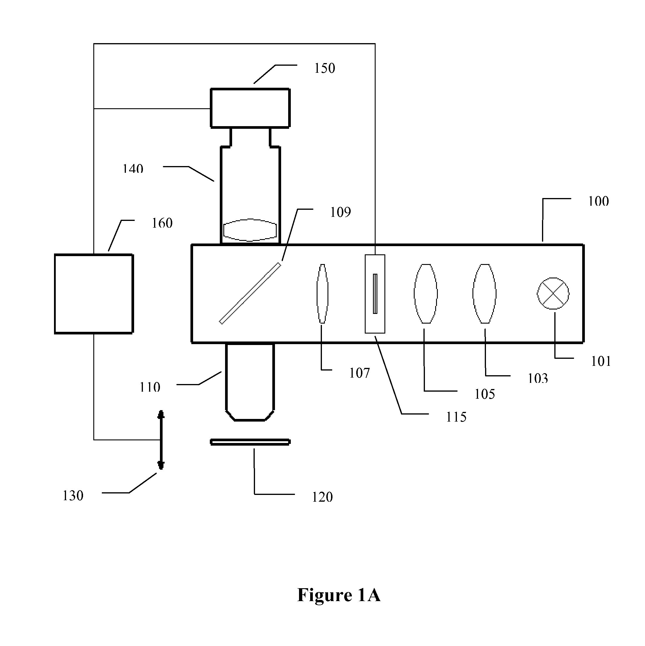
[0032]FIG. 1A is a diagram illustrating a 3-D optical microscope with a reflective illuminator in accordance with the present invention. A microscope operating in reflective illumination mode is often used for studying opaque samples such as a semiconductor wafer. Reflective illuminator 100 provides illumination for the microscope and contains several components. Light source 101 generates illuminating light. Among possible choices for the light source are: a lamp, a fiber coupled light, a LED light, a laser, and etc. In the preferred embodiment, either a halogen lamp or a fiber coupled light source is used. Lenses 103, 105, and 107 ensure uniform illumination on sample 120 and, when pattern generator 115 is placed in the illuminator optical path, project an image of a patterned article to the focal plane of objective lens 110. Beam-splitter 109 is mounted at a 45° angle with respect to a centerline connecting lenses 103, 105, and 107 so that light from the light source is directed ...

third embodiment

[0074]the present invention, shown in FIG. 7, is a 3-D optical microscope with a transmitted illuminator. A microscope operating in transmitted illumination mode is often used for studying transparent objects such as biology related samples. Transmitted illuminator 700 provides illumination for the microscope and contains several components. Light source 701 generates illuminating light. Among possible choices for the light source are: a lamp, a fiber coupled light, a LED light, a laser, and etc. In the preferred embodiment, either a halogen lamp or a fiber coupled light source is used. Lenses 703, 705, 707, and 711 ensure uniform illumination on sample 720 and, when pattern generator 115 is placed in the illuminator optical path, project an image of the patterned article to the focal plane of objective lens 710. Beam-splitter 709 is mounted at a 45° angle with respect to a centerline connecting lenses 703 and 705 so that light from the light source is directed vertically upward to ...

fifth embodiment

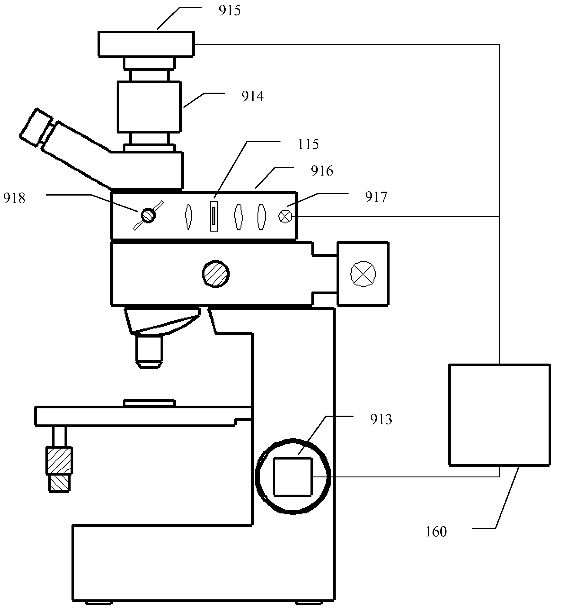
[0080]FIG. 9B illustrates modifications made to a conventional microscope of FIG. 9A in order to turn it into a 3-D optical microscope in accordance with the present invention. F-stop 902 of FIG. 9A is replaced by pattern generator 115 of FIG. 1A. Means for focusing adjustment 913 is implemented either on fine focus knob 909 or on objective turret 903 of FIG. 9A. Some examples of means for focusing adjustment are electrical motor, piezoelectric actuator, and etc. In the preferred embodiment, means for focusing adjustment 913 is a motor coupled to fine focus knob 909 of FIG. 9A. It is understood that other means of focusing adjustment is also within the scope of the present invention. Coupler 914 is mounted on trinocular tube 911 and camera 915 is attached to coupler 914. Finally, processor 160 is connected to the modified microscope of FIG. 9B. The processor is used to control means for focusing adjustment 913, camera 915, and pattern generator 115. In addition, said processor analy...


PUM


Abstract

A 3-D optical microscope, a method of turning a conventional optical microscope into a 3-D optical microscope, and a method of creating a 3-D image on an optical microscope are described. The 3-D optical microscope includes a processor, at least one objective lens, an optical sensor capable of acquiring an image of a sample, a mechanism for adjusting focus position of the sample relative to the objective lens, and a mechanism for illuminating the sample and for projecting a pattern onto and removing the pattern from the focal plane of the objective lens. The 3-D image creation method includes taking two sets of images, one with and another without the presence of the projected pattern, and using a software algorithm to analyze the two image sets to generating a 3-D image of the sample. The 3-D image creation method enables reliable and accurate 3-D imaging on almost any sample regardless of its image contrast.

Description

FIELD OF THE INVENTION[0001]This invention relates generally to an optical microscope and, more particularly, to a three-dimensional (3-D) optical microscope, and a method of turning a conventional optical microscope into a 3-D optical microscope.BACKGROUND OF THE INVENTION[0002]A conventional microscope enables an operator to view magnified images of minute features on a sample otherwise invisible to the human eye. Because of this, conventional microscopes have been widely used in universities, in research institutes, and in many industries. A conventional microscope, however, has important limitations. For example, it only provides a two-dimensional (2-D) image of a sample while in the real world a majority of samples are 3-D in nature.[0003]Various improvements have been made over the years to achieve 3-D viewing and 3-D imaging with optical microscopes. Costales in U.S. Pat. No. 6,275,335 discloses a stereomicroscope using various polarizing optical components to achieve a stere...

Claims


Application Information

Patent Timeline
Patent Type & Authority Patents(United States)
IPC IPC(8): G02B21/00
CPCG02B21/06H04N13/0253H04N13/0207G02B21/367H04N13/254H04N13/207
Inventor XU, JAMES JIANGUOLEE, KEN KINSUN
Owner KLA CORP
Why Eureka
Try Eureka