
Optical beam flattening using multi-mode fiber

a multi-mode fiber and optical beam technology, applied in the field of optical transmission, can solve the problems of inefficient energy delivery to the target, excess power being transmitted on the bore sight, unused power being transmitted outside the region, etc., and achieve the effect of improving manufacturing accuracy and reducing the transmitted power

Inactive Publication Date: 2010-06-01
BAE SYST INFORMATION & ELECTRONICS SYST INTEGRATION INC
View PDF6 Cites 18 Cited by
  • Summary
  • Abstract
  • Description
  • Claims
  • Application Information

AI Technical Summary

Benefits of technology

[0011]One embodiment of the present invention transmits a top-hat shaped beam profile which reduces the transmitted power required for FSO Com and IRCM and improves accuracy for manufacturing.

Problems solved by technology

If that power level is exceeded, the additional power is unnecessary and wasted.
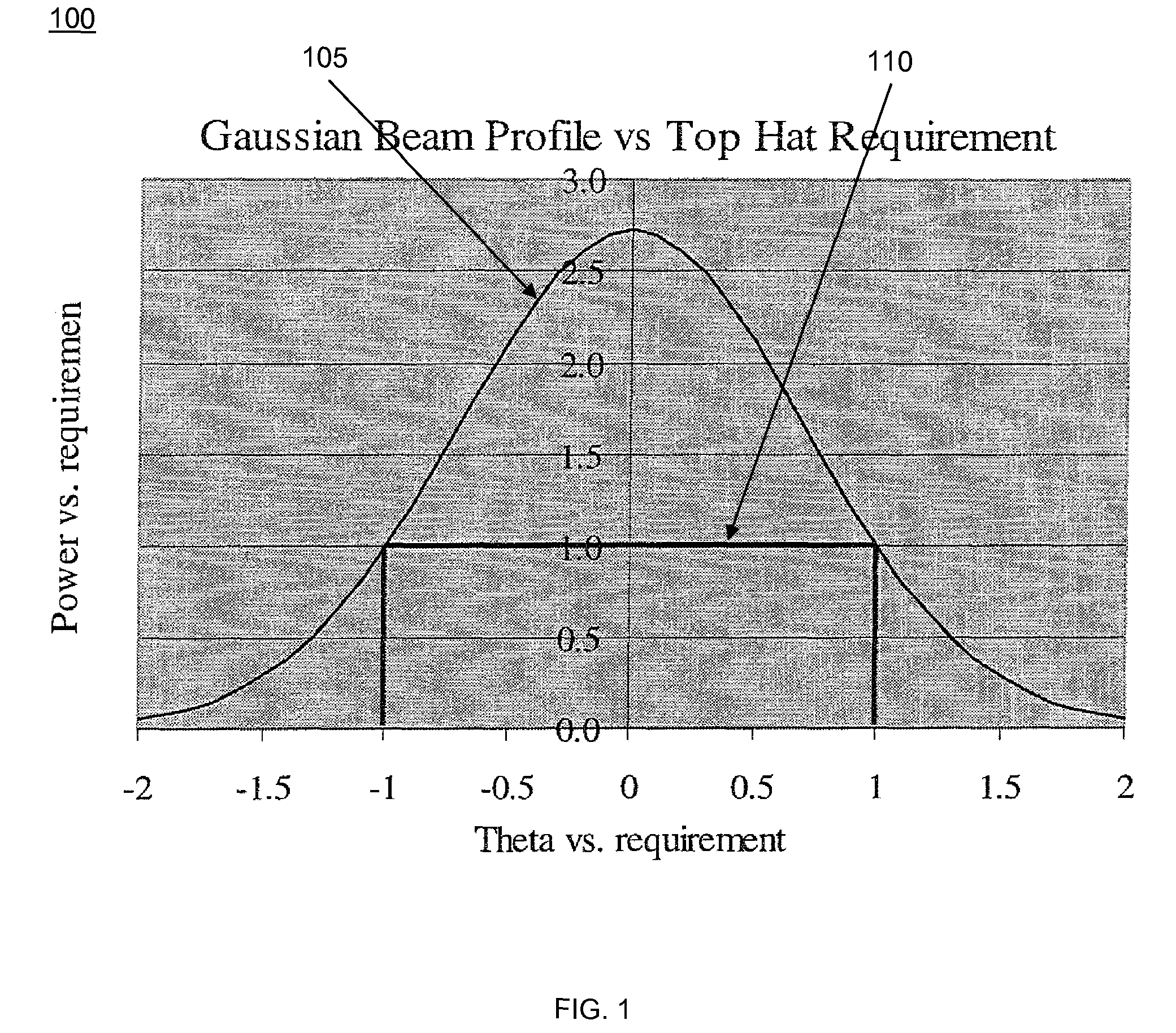
The result is excess power being transmitted on bore sight and unused power being transmitted outside the region of interest.
Each application exhibits inefficient energy delivery to the target.
Disadvantages are that the Gaussian profile wastes power for infrared countermeasures (IRCM) and free space optical (FSO) communications and limits accuracy for laser drilling and cutting.

Method used


Image

  • Optical beam flattening using multi-mode fiber
  • Optical beam flattening using multi-mode fiber
  • Optical beam flattening using multi-mode fiber

Examples


Embodiment Construction

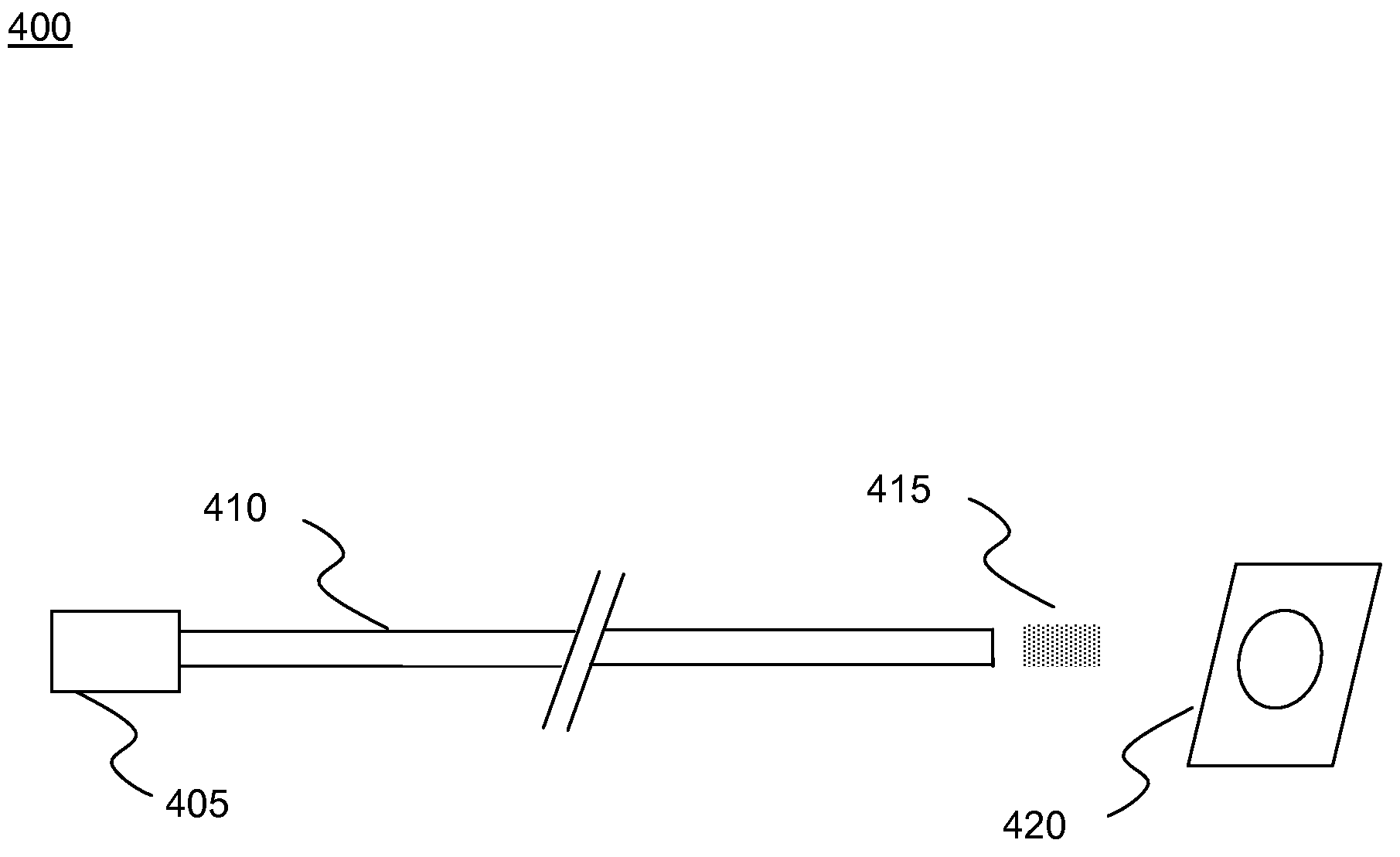
[0026]An optical transmission system far-field intensity distribution is a function of fiber cladding diameter, spool diameter, the number of fiber loops, and the wavelength of the light.

[0027]The transmission mode of single mode fiber (SMF) is Gaussian. The widths of far-field Gaussian beams are such that at the edge of the required solid angle, the power must exceed a required amount. The result is excess power being transmitted on bore sight and unused power being transmitted outside the region of interest.

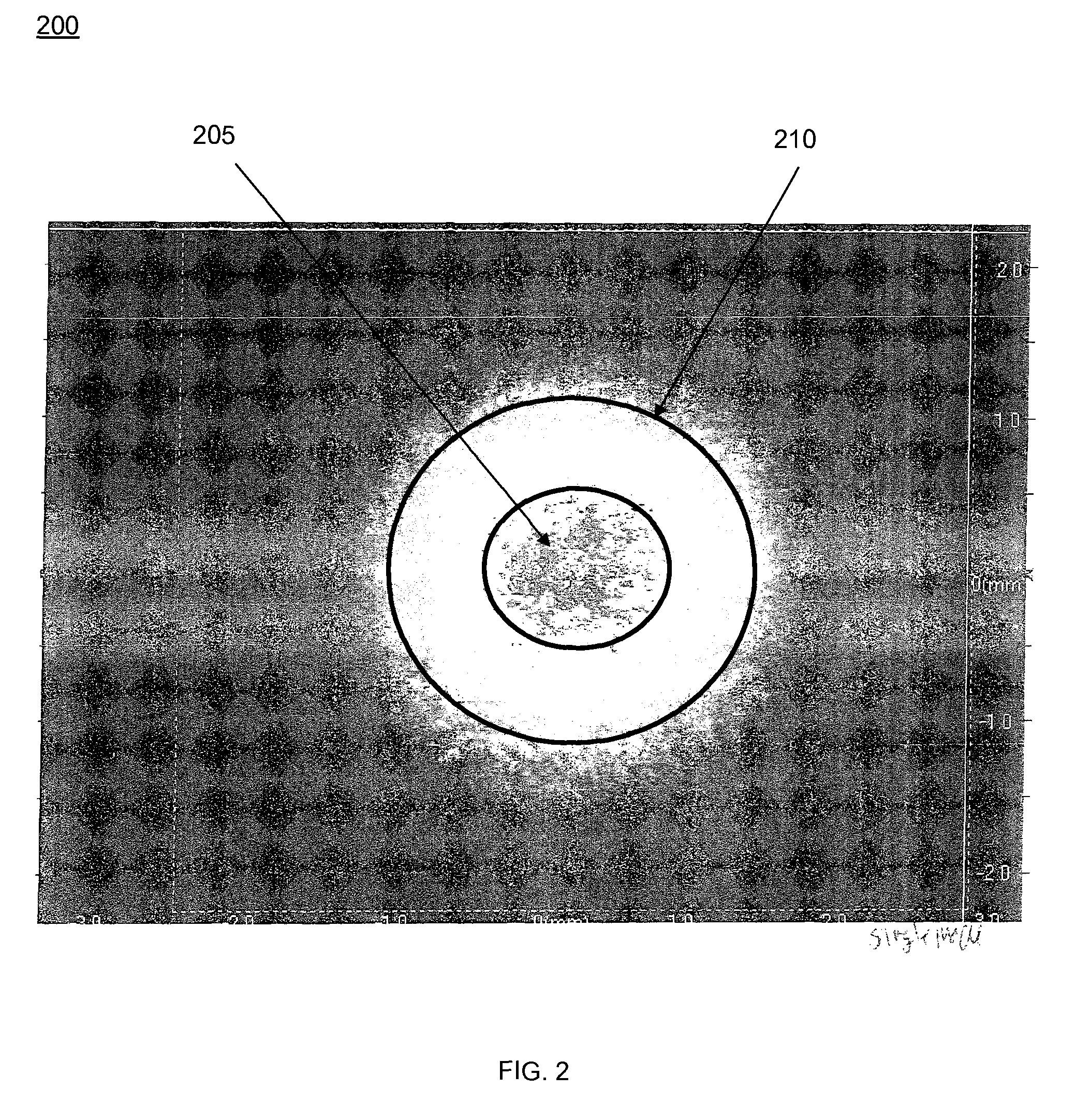
[0028]By recognizing that the far-field pattern is the Fourier transform of the mode field pattern within the beam director, it is desirable to create a Bessel function (essentially a sinc function in cylindrical coordinates) which results in a top-hat intensity in the far-field.

[0029]Regarding the far-field, a criterion for IRCM is that targets be in the far-field of the transmitter. In the far-field, light waves are parallel. The target range can be deduced as R=D2 / λ where D ...


PUM

PropertyMeasurementUnit
lengthsaaaaaaaaaa
lengthsaaaaaaaaaa
optical signalaaaaaaaaaa

Abstract

The present invention includes a device and method to create a light beam having substantially uniform far-field intensity. Light from a laser source is directed to at least one multimode optical fiber configured produce an intensity profile approximated by a Bessel function.

Description

[0001]This application claims the benefit of U.S. Provisional Application No. 60 / 992,758 filed Dec. 6, 2007. This application is herein incorporated in its entirety by reference.STATEMENT OF GOVERNMENT INTEREST[0002]The present invention was made under Contract No. N00173-05-C-6020 awarded by the US Navy—Navy Research Lab, and the United States Government has certain rights in this invention.FIELD OF THE INVENTION[0003]The invention relates to optical transmission, and more particularly, to non-Gaussian far-field intensity profiles generated with multimode optical fiber.BACKGROUND OF THE INVENTION[0004]Existing fiber optic transmission media have employed single mode fiber coupled to free space. Standard single mode fiber produces a Gaussian field radiation profile and a Gaussian far-field beam.[0005]Applications of transmitted optical beams include infrared countermeasures (IRCM), free space optical communications (FSO Com) and laser cutting and drilling for manufacturing.[0006]In ...

Claims


Application Information

Patent Timeline
Patent Type & Authority Patents(United States)
IPC IPC(8): G02B6/26B23K26/00
CPCG02B6/0288G02B27/0927H01S3/005G02B27/0994H01S2301/206
Inventor MORIARTY, DANIEL T
Owner BAE SYST INFORMATION & ELECTRONICS SYST INTEGRATION INC
Learn More