Display method for multiple layered screens

a display method and screen technology, applied in the direction of instruments, user interface execution, static indicating devices, etc., can solve the problems of limited screen area available, related problems experienced by software users, and objects at the back of the picture being obscured

Inactive Publication Date: 2010-06-01
APTIV TECH LTD
View PDF235 Cites 96 Cited by
  • Summary
  • Abstract
  • Description
  • Claims
  • Application Information

AI Technical Summary

Benefits of technology

[0014]According to one aspect of the present invention there is provided a method for creating a visual effect in the display of software in a multilevel screen display formed by pixels whereinthe software is for the presentation of data or images on a screen using software functions,the method characterised by the steps of
[0027]This arrangement of layering multiple screens allows images to be presented at multiple levels giving the viewer true depth without use of glass or lens.
[0030]With the present invention, a screen designation code may be used to place all of the standard software functions, templates, tool bars and the like on the foreground screen. However, the image being worked upon may be placed on the background screen. This arrangement allows the user of the software to effectively look behind the foreground components to view the image being manipulated.
[0032]Thus, there is now no requirement for the user to move around on screen various toolbars and the like so as to get a full view of the image.
[0034]To allow the drawings components to be readily and / or manipulated, the components themselves may have different transparencies. Further, the traditional white palette may be fully transparent.
[0037]The interface maybe a patch for existing software, a display driver, a library file or a new front end for multiple existing software packages or a completely new operating system. Instead of software, graphic cards may be used to divide the images appropriately. This will increase the speed of operation considerably.

Problems solved by technology

The reason for this is that there is only limited screen area available.
Often, the user is placed in the undesirable position of having to move around the tool bars and menus if possible, or alternatively move the drawing (or whatever file the user is working on) so that the user can actually see parts of the drawing formerly obscured by the menus and so forth.
There is another related problem experienced by software users, particularly in relation to drawing packages, but not exclusively.
This can in some cases lead to the objects at the back of the picture being obscured by larger objects at the front of the picture.
Thus, the user cannot readily select the object at the back of the picture with it being obscured.
This is understandably frustrating and can impede the users' ability to work efficiently, often requiring the user to move the front object so as to gain access to the back object.
It can also be frustrating to not having ready access to the multiple levels in such diverse applications as geographical information system (GIS) programs, including medical models, instrumentation using browsers for the internet or game software, for example flight simulators.

Method used


Image

  • Display method for multiple layered screens
  • Display method for multiple layered screens
  • Display method for multiple layered screens

Examples


Embodiment Construction

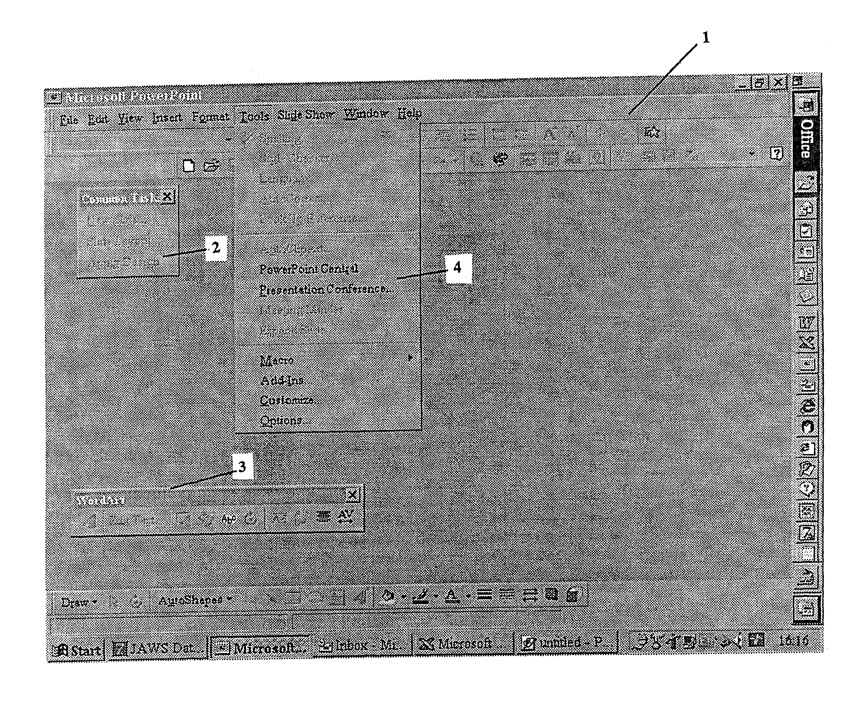
[0049]With respect to FIG. 1, there is illustrated a typical screen display found in commercial software, in this case, the commercial software is Microsoft Powerpoint™.

[0050]On this display there is an external template (1), two toolbars (2, 3), a drop down menu (4) and an image to be manipulated (5) on a palette (6).

[0051]It can be seen that the toolbars (2, 3) and drop down menu (4) obscure the image (5) and palette (6).

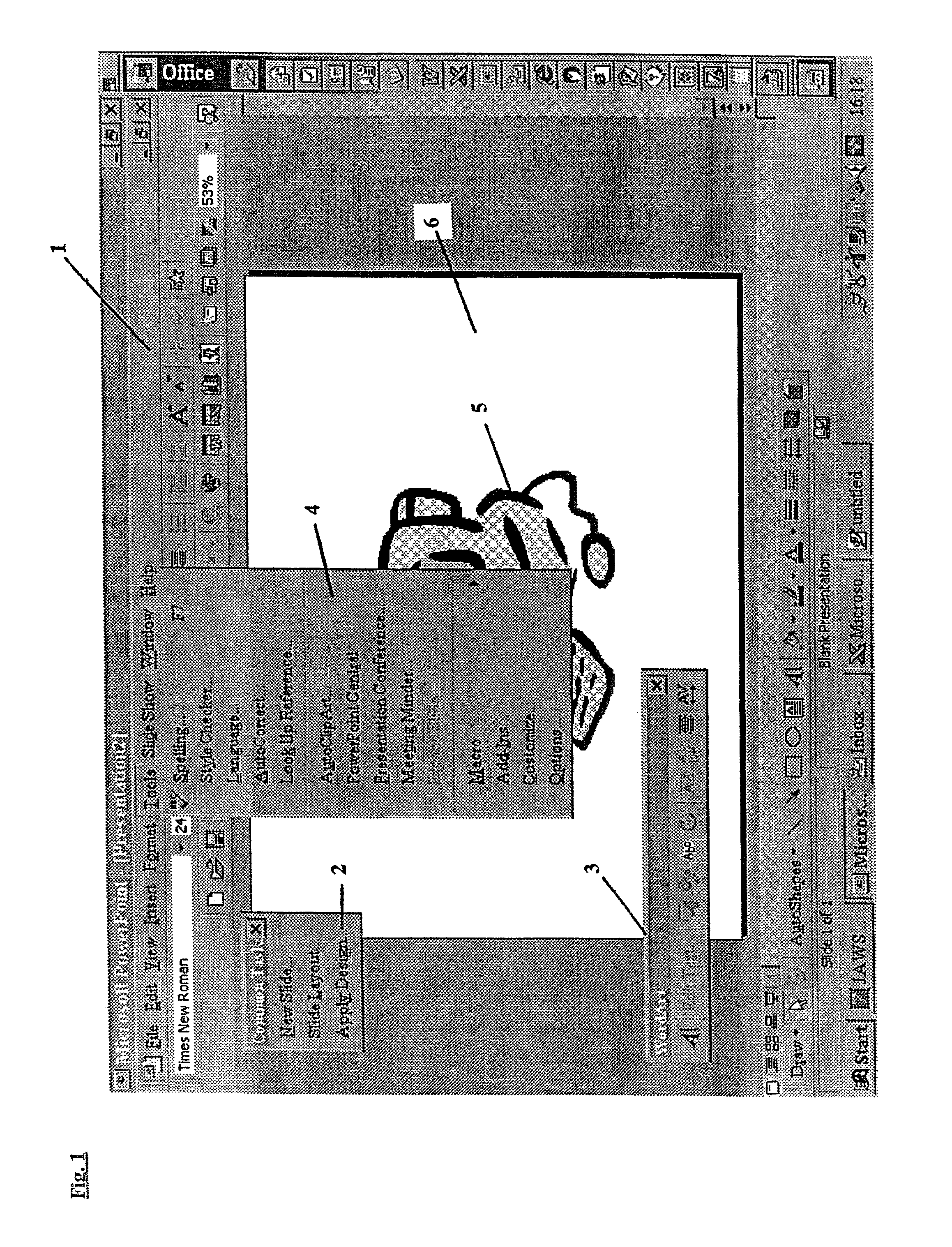
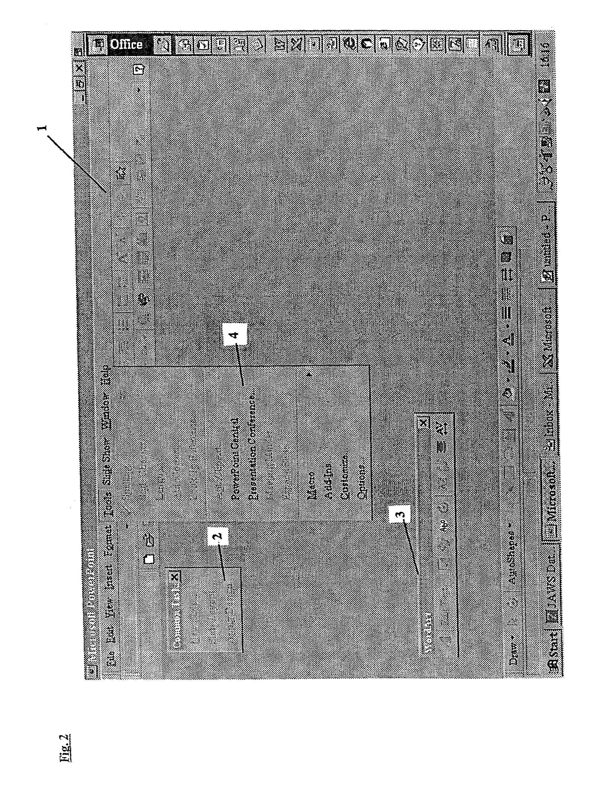
[0052]With the present invention, the common components of the software can be placed on the foreground screen of a multi-level screen display as illustrated in FIG. 2. It should be noted that the palette (6) and the image (5) are not displayed on the foreground screen.

[0053]Instead, the image (5) is displayed on a background screen as illustrated in FIG. 3. With the present invention there is no need to display a palette.

[0054]The separation of the image (5) from the standard software components (1, 2, 3 and 4) is achieved by the present invention assigning scree...


PUM

PropertyMeasurementUnit
depth relationshipaaaaaaaaaa
depthaaaaaaaaaa
transparencyaaaaaaaaaa

Abstract

A method of displaying data or images on a multi-level screen display, assigns screen designation codes to respective software components, to determine the physical screen on which the corresponding images or software components are displayed. The screens may include layered liquid crystal displays. The method allows a user to see overlaying objects at the same time, e.g., toolbars or menus can be displayed on a front screen, and a drawing image can be displayed on a background screen.

Description

TECHNICAL FIELD[0001]This invention relates to software visual effects.BACKGROUND ART[0002]Many software programs these days display information on a screen using effectively a multi-layered approach.[0003]For example, a drawing package may have a central area which the software user can draw upon.[0004]In a typical drawing package there are many drop down menus, tool bars, cursors or templates which effectively overlay the drawing on the screen. The reason for this is that there is only limited screen area available. Thus, for the user to be able to view the functions to be selected, some of the drawing space has to be borrowed for this.[0005]Often, the user is placed in the undesirable position of having to move around the tool bars and menus if possible, or alternatively move the drawing (or whatever file the user is working on) so that the user can actually see parts of the drawing formerly obscured by the menus and so forth.[0006]There is another related problem experienced by ...

Claims


Application Information

Patent Timeline
Patent Type & Authority Patents(United States)
IPC IPC(8): G06F3/00G02F1/133G09F5/00G06F3/14G06F9/44G06T11/60G09G3/20G09G3/36G09G5/14G09G5/397
CPCG06F9/4443G09G5/14G06T11/60G09G2300/023G06F9/451
Inventor ENGEL, GABRIEL DAEMONWITEHIRA, PITA
Owner APTIV TECH LTD
Why Eureka
Try Eureka