Situ system and method for treating an oil and gas well drilling fluid

a technology for oil and gas wells and fluids, applied in the field of system and method for treating wastewater, can solve the problems of cleaning drilling fluids, affecting the efficiency of drilling fluids, and requiring years for water to evaporate and prior, so as to reduce the cost

Inactive Publication Date: 2010-06-08
H2O TECH
View PDF16 Cites 39 Cited by
  • Summary
  • Abstract
  • Description
  • Claims
  • Application Information

AI Technical Summary

Benefits of technology

[0009]In view of the foregoing, it is a primary objective of the subject invention to treat a drilling fluid in a reserve pit and create a pure form of water that can be reused in a drilling operation reducing the cost of hauling water to the drilling site or discharged into a ground surface without violating state and federal environmental regulations. Also, the system can be used on treating water produced from an oil and gas well after the well is completed and production begins.

Problems solved by technology

The treating and cleaning of drilling fluids from an oil and gas well drilling operation has long been a problem waiting for a solution.
This solution can take years for the water to evaporate and prior to burying the remaining solids left in the pit.
Also, animals and birds can be trapped in the pit during the time the pit is left open and exposed.
At this time, less and less water evaporation occurs and the fluid becomes more dense until it can no longer be pumped effectively.
Chemical treatment of the drilling fluid can be employed to remove solids, but the water phase of the fluid is loaded with salt and dissolved minerals that make the water undesirable for further use.
Solidification of the drilling fluid is an option, but this leaves a potential environmental danger if rain or surface water disturbs the site during subsequent time periods.
Therefore and because the above-mentioned systems and methods are ineffective in removing all of the contaminates in a drilling fluid, there is no single technology that will solve the overall problem.

Method used


Image

  • Situ system and method for treating an oil and gas well drilling fluid
  • Situ system and method for treating an oil and gas well drilling fluid
  • Situ system and method for treating an oil and gas well drilling fluid

Examples


Embodiment Construction

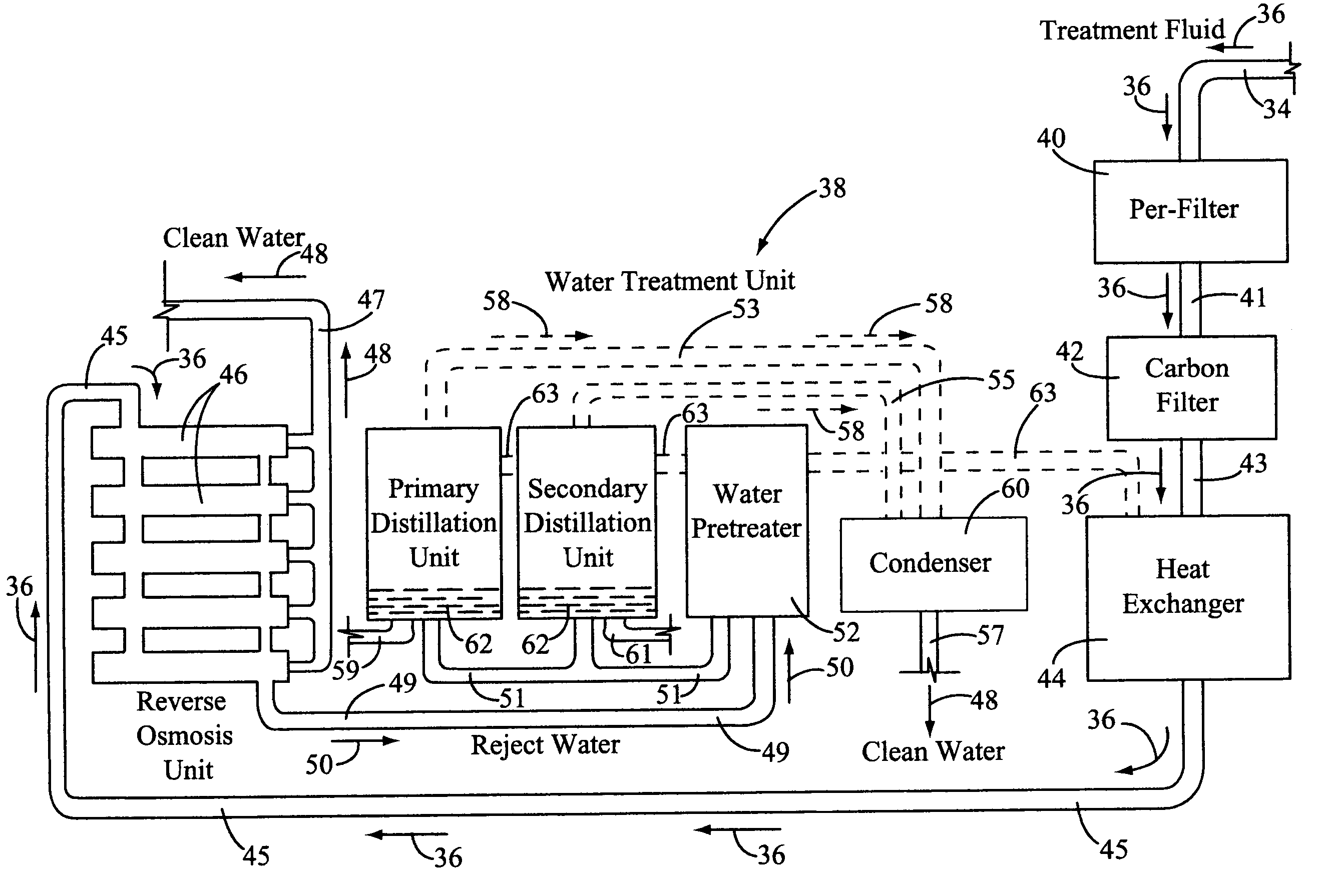
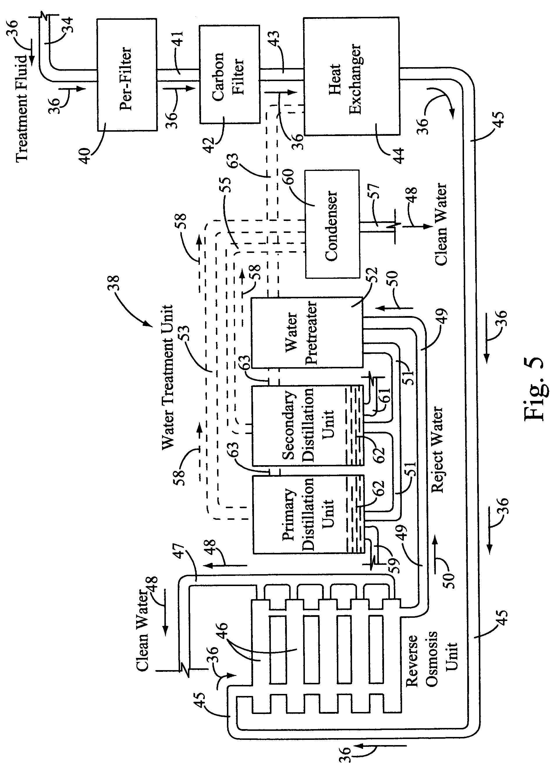
[0029]At the start of the drilling fluid cleaning process, the fluid in a reserve pit is first analyzed to determine the amount of solids in the pit and the pH of the fluid in the pit. If necessary, an acid or caustic can be added to the pit to bring the pH into a most effective range for the system and method to work as efficiently as possible. Generally, the pH needs to be between 5 and 8. A test is run on a bench scale electrocoagulation unit on one gallon of fluid. This test will demonstrate the results that will be produced by the first step of using the electrocoagulation unit in the pit and indicate the amount of watt hours of electricity needed per gallon of fluid. Based on this information, a mathematical determination can then be made of the amount of watt hours needed to treat the entire reserve pit. A typical pit may contain from 10,000 to 50,000 ppm of total solids and as much as 5,000 to 15,000 ppm of salt. A heat exchanger is employed in the system to utilize waste he...


PUM

PropertyMeasurementUnit
solutionaaaaaaaaaa
timeaaaaaaaaaa
surface tensionaaaaaaaaaa

Abstract

An in situ system used for treating an oil and gas well drilling fluid and treating water after a well is completed. The system includes a fluid treatment unit used in a reserve pit and a water treatment unit disposed next to the pit. The fluid treatment unit includes a floating electrocoagulation unit in the reserve pit for destabilizing contaminates in the fluid and dropping out stable precipitates. The clear treated fluid is then pumped, using a submersible pump, to the water treatment unit. The water treatment includes a number of components including a pre-filter, an activated carbon filter and a heat exchanger for first treating the fluid. The filtered and heated fluid is then piped into a reverse osmosis unit for removing salt and any remaining minerals found therein. From the reverse osmosis unit, approximately 70 to 80% of the filtered water is cleaned and piped to a clean water storage tank for reuse. Reject water from the reverse osmosis unit is transferred to a water pre-heater and a primary and secondary distillation unit for converting the heated water to steam. The steam is now piped to a condenser where the steam is cooled to distilled, clean water. The remaining clean water from the condenser is now transferred to the clean water storage tank.

Description

BACKGROUND OF THE INVENTION[0001](a) Field of the Invention[0002]This invention relates to a system and a method for treating wastewater from an oil and gas drilling operation and more particularly, but not by way of limitation, to an in situ system and method for treating an oil and gas well drilling fluid next to a drilling site and greatly reducing various types of contaminates held in suspension in the fluid and creating reusable water for addition drilling or discharge into a ground surface without violating any environmental state and federal regulations.[0003](b) Discussion of Prior Art[0004]The treating and cleaning of drilling fluids from an oil and gas well drilling operation has long been a problem waiting for a solution. One typical solution is to allow the water to evaporate from a reserve pit next to the drilling rig. This solution can take years for the water to evaporate and prior to burying the remaining solids left in the pit. Also, animals and birds can be trapped...

Claims


Application Information

Patent Timeline
Patent Type & Authority Patents(United States)
IPC IPC(8): B01D61/00B01D17/06B01D63/00C07C1/00C02F1/46
CPCB01D61/025B01D61/04E21B21/06C02F9/00C02F2303/24C02F2103/10C02F1/463C02F1/441C02F1/283C02F1/16B01D2311/04B01D2311/08C02F1/02C02F1/048B01D2311/2684B01D2311/2649B01D2311/2626B01D2311/26B01D2311/2669
Inventor HERBST, ROBERT J.
Owner H2O TECH
Why Eureka
Try Eureka