Detent changeover switch apparatus

a switch and switch technology, applied in the direction of contact mechanisms, mechanical control devices, instruments, etc., can solve the problems of increasing the number of parts needed for the rotary switch, increasing the cost of the device, or affecting the operation of the switch

Inactive Publication Date: 2010-06-08
KK TOKAI RIKA DENKI SEISAKUSHO
View PDF4 Cites 68 Cited by
  • Summary
  • Abstract
  • Description
  • Claims
  • Application Information

AI Technical Summary

Benefits of technology

[0007]It is an object of the present invention to provide a detent changeover switch apparatus which can change over click feeling generated by one operation switch with the small number of parts even when click feeling of an operation portion can be changed over in multiple stages.
[0025]This arrangement adopts the structure in which, in incorporating the detent changeover mechanism for changing over the click feeling of the operation portion into the operation switch apparatus, the plurality of concave / convex patterns necessary in such a case is formed on one detent crest member, and one concave / convex pattern is selected out of the concave / convex patterns as the concave / convex pattern used for each case. Accordingly, assuming a case in which the detent crest member is provided for every concave / convex pattern, the number of parts is increased correspondingly thus giving rise to a possibility that the operation switch apparatus becomes large-sized, a parts cost is increased or the like. However, by mounting the plurality of concave / convex patterns on one detent crest member as in the case of this arrangement, it is unnecessary to prepare the detent crest member for every concave / convex pattern and hence, there is substantially no possibility that the operation switch apparatus becomes large-sized or a parts cost is increased.
[0026]With this arrangement, for example, when a linear actuator which reciprocally and linearly moves the drive shaft is used as the drive source of the detent changeover mechanism, it is necessary to provide a moving space for the drive shaft in the inside of the operation switch apparatus thus giving rise to a possibility that the device becomes large-sized correspondingly. However, using the rotary actuator as the drive source of the detent changeover mechanism as in the case of this arrangement, this kind of motor is rotated at the own position and hence, a small space is required as the arrangement space thus substantially eliminating the possibility that the device becomes large-sized.
[0027]With this arrangement, the plurality of concave / convex patterns present for generating the click feelings which differs from each other is formed in a state that the plurality of concave / convex patterns is arranged side by side in the radial direction with respect to the detent crest member performing the rotary movement along with the operation of the operation portion. Accordingly, the part size of the detent crest member can be decreased in the direction of the operation axis of the operation portion and hence, the device size of the operation switch apparatus in the direction of the operation axis can be decreased.

Problems solved by technology

Accordingly, although the operation switch described in JP-A-2002-189559 can change over the click feeling of the dial knob, the number of parts necessary for the rotary switch is increased thus giving rise to a possibility that the switch apparatus becomes large sized or a device cost is pushed up whereby there has been a demand for the reduction of the number of parts of this kind.

Method used


Image

  • Detent changeover switch apparatus
  • Detent changeover switch apparatus
  • Detent changeover switch apparatus

Examples


first embodiment

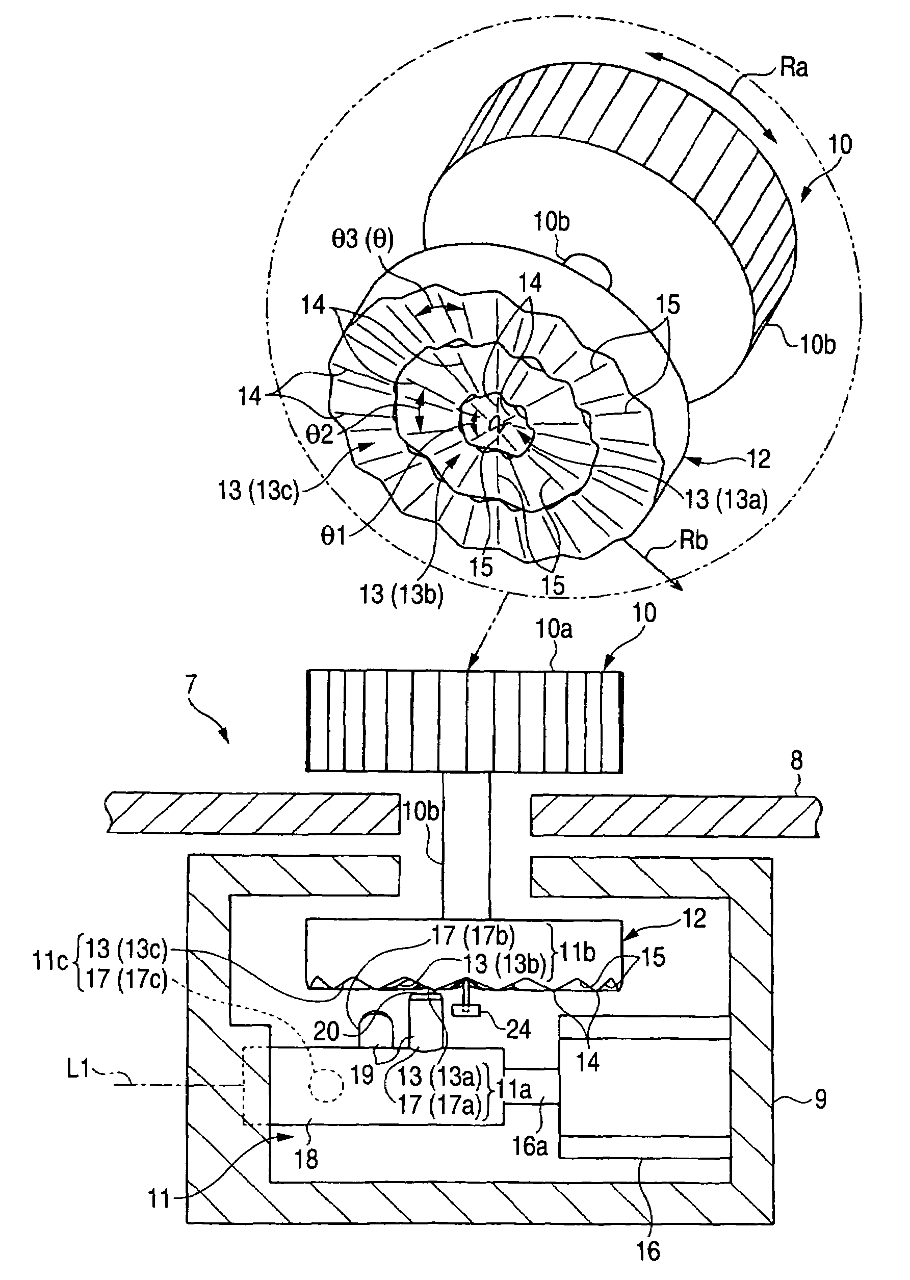
[0044]A first embodiment of a detent changeover switch apparatus which embodies the present invention is explained in conjunction with FIG. 1 to FIG. 9 hereinafter.

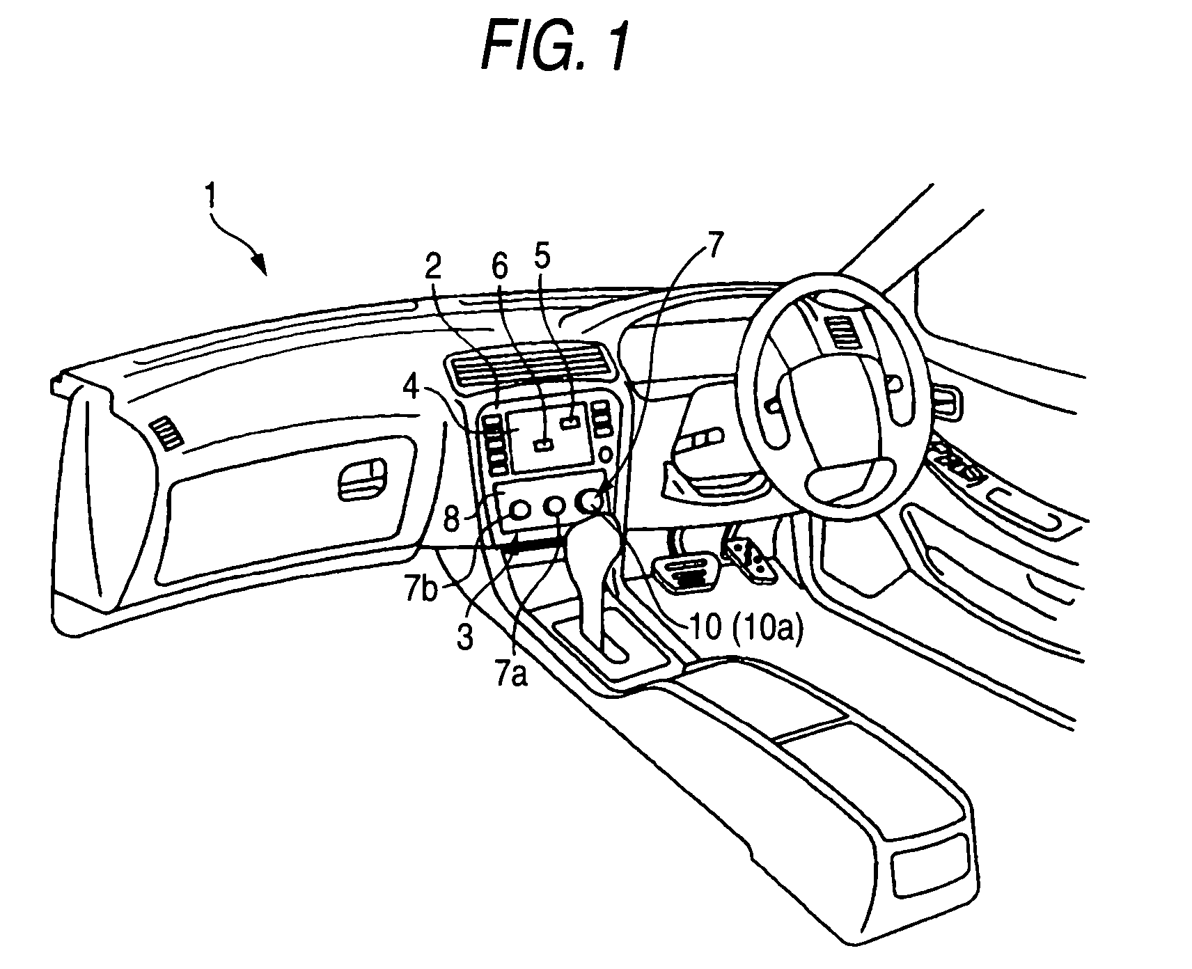
[0045]As shown in FIG. 1, on a center cluster 2 of a vehicle 1, an operation switch apparatus 3 is mounted as an operation system of various vehicle loaded equipment such as an air conditioner, an audio device and a car navigation device. The operation switch 3 of this embodiment uses a graphical user interface (GUI) for enhancing visibility and operability at the time of performing a button selection operation. The graphical-user-interface-type operation switch apparatus 3 performs a graphic display of item buttons 5, icons 6 and the like on a display 4 mounted on the center cluster 2 and, while selectively designating the item buttons 5, the icons 6 or the like on the display 4 using an operation switch 7 mounted on the same center cluster 2, performs an input operation using a decision switch 7a and a return switch 7b ...

second embodiment

[0085]Next, the second embodiment is explained in conjunction with FIG. 11 and FIG. 12. Here, the second embodiment is substantially equal to the first embodiment except for that only the structure of the detent changeover mechanism 11 of the second embodiment differs from the detent changeover mechanism 11 of the first embodiment. Accordingly, parts identical with the parts of the first embodiment are given same symbols, and their detailed explanation is omitted, and only parts which differ from the parts of the first embodiment are explained.

[0086]As shown in FIG. 11, to a distal end of a drive shaft 16a of a motor 16, a columnar plunger selection portion 39 is fixedly secured in a state that the plunger selection portion 39 is integrally rotatably with the motor 16 coaxially with the drive shaft 16a. Pushing portions 40 having an arcuate cross-sectional shape are formed on an outer peripheral surface of the plunger selection portion 39, wherein the number of pushing portions 40 i...


PUM


Abstract

A detent crest member is integrally rotatably mounted on a dial knob. On the other hand, on a peripheral surface of a plunger mounting member which is rotatably operated using a motor, a plurality of plunger members which generates clicks in a dial knob together with the detent crest member is mounted. In changing over click feeling, the motor is rotated thus selectively bringing one of the plunger members mounted on the plunger mounting member into resilient contact with concave / convex patterns of the detent crest member which form the pair with one plunger member.

Description

BACKGROUND OF THE INVENTION[0001]The present invention relates to a detent changeover switch apparatus capable of changing over click feeling generated by an operation portion of an operation switch.[0002]Conventionally, as an input operation system for performing operation setting of various vehicle-loaded equipment such as an air conditioner and an audio device, various kinds of operation switches are mounted on a vehicle corresponding to respective functions. As one example, with respect to the operation switches of the air conditioner, for example, a temperature setting switch for setting a supply-air temperature, an air volume setting switch for setting an air volume, an air blow direction setting switch for setting an air blow and the like are used. As such a group of switches, a rotary operation switch, that is, a rotary switch which performs setting of various functions by rotatably operating a dial knob of a rotary operation type as an operation portion has been popularly u...

Claims


Application Information

Patent Timeline
Patent Type & Authority Patents(United States)
IPC IPC(8): H01H13/62
CPCB60K37/06G06F3/0362G05G5/03G05G1/10B60K2350/102B60K2370/126B60K2370/158
Inventor OTANI, KAZUYAISHIGAKI, SEIJI
Owner KK TOKAI RIKA DENKI SEISAKUSHO
Why Eureka
Try Eureka