Systems, methods and apparatus for preparation, delivery and monitoring of radioisotopes in positron emission tomography

a technology of positron emission tomography and control system, which is applied in the direction of local control/monitoring, radiometric measurement, railway signalling, etc., can solve the problems of pet technicians being exposed to radioactivity, a large amount of packaging and transportation of heavy containers twice a day, and a large amount of radioactivity exposur

Active Publication Date: 2010-06-08
GENERAL ELECTRIC CO
View PDF49 Cites 91 Cited by
  • Summary
  • Abstract
  • Description
  • Claims
  • Application Information

AI Technical Summary

Benefits of technology

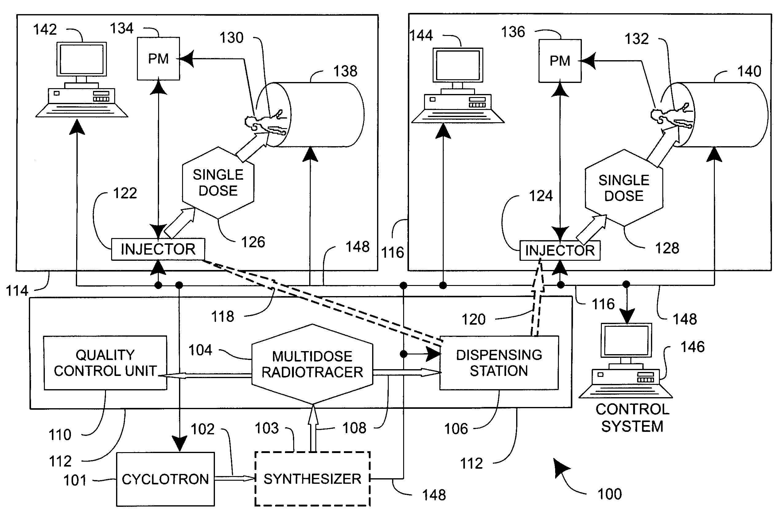
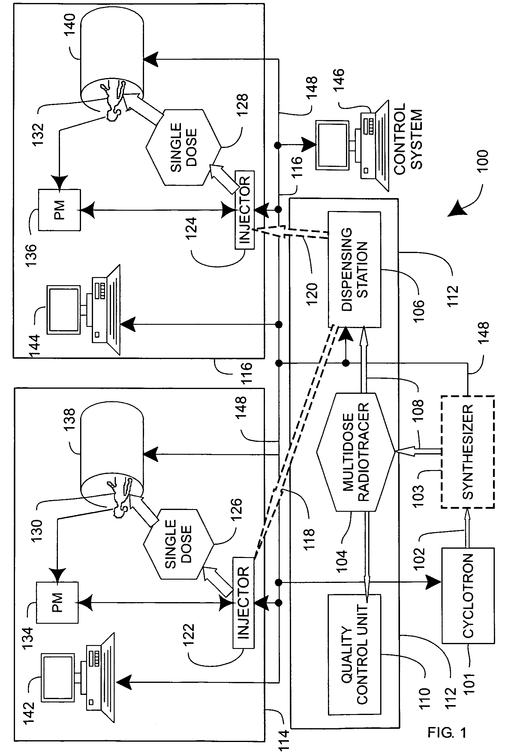
[0012]In one aspect, a system includes a local area network that is operably coupled to one or more positron emission tomography imaging systems. The system also includes a dispensing station that is operable to receive a multidose portion or vial of a radiopharmaceutical. The dispensing station is operable to dispense portions of the radiopharmaceutical to the one or more positron emission tomography imaging system. The dispensing station is also operably coupled to the local area network. The dispensing station dispenses a radiopharmaceutical in the patients who are subsequently imaged using the positron emission tomography imaging systems. The dispensing station allows a multidose portion of the radiopharmaceutical to be dispensed to the patients, which provides economies of scale and a convenient way of distribution of the radiopharmaceutical.

Problems solved by technology

The cost and overhead of preparing individual dose vials, packaging and transporting a number of the heavy containers twice a day is significant.
In addition, when the radiopharmaceutical is administered to the patient, the PET technician is exposed to radioactivity.
This close proximity to the radioactivity results in numerous low levels of exposure to radioactivity that can be harmful to the health of the PET technician.
Furthermore, conventional systems can be slow, which requires that the radioisotope material must be produced at a much stronger level of radioactivity in order to have the required amount of radioactivity at the time of injection.
Therefore, the use of nitrogen-13 ammonia and oxygen-15 for PET is limited to those sites that have immediate access to its production.

Method used


Image

  • Systems, methods and apparatus for preparation, delivery and monitoring of radioisotopes in positron emission tomography
  • Systems, methods and apparatus for preparation, delivery and monitoring of radioisotopes in positron emission tomography
  • Systems, methods and apparatus for preparation, delivery and monitoring of radioisotopes in positron emission tomography

Examples


an embodiment

Methods of an Embodiment

[0099]In the previous sections, a system level overview of the operation of an embodiment was described and embodiments of apparatus were described. In this section, the particular methods performed by PET technologists and the control system 146 of such an embodiment are described by reference to a series of flowcharts. Describing the methods by reference to a flowchart enables one skilled in the art to develop manual procedures or computer instructions.

[0100]FIG. 7 is a flowchart is an embodiment of a method 700 of operation of apparatus 400. Method 700 is performed by a PET technologist. Typically, method 700 is performed once for each day of operation of a PET scanning system.

[0101]A PET technologist prepares system 400 for use by a number of patients in action 702, which is described in greater detail in FIG. 8. Then system 400 is repeatedly prepared 704 for each individual patent as described in FIG. 9 and the injection for each patient is administered ...


PUM


Abstract

In one aspect, systems, methods and apparatus are provided through which a dispensing station dispenses a large quantity of a radiotracer to one or more positron emission tomography imaging stations. In some aspects a quality control unit verifies the quality of the radiotracer. In some embodiments, components of the system are coupled by a local area network. In some aspects, each positron emission tomography imaging station includes an injector system, a physiological monitoring device, and a positron emission tomography scanner. All of the devices can be controlled by a computer system.

Description

RELATED APPLICATION[0001]This application is related to copending U.S. application Ser. No. 10 / 792,683, filed Mar. 2, 2004 entitled “Systems, methods and apparatus for infusion of radiopharmaceuticals.”FIELD OF THE INVENTION[0002]This invention relates generally to positron emission tomography, and more particularly to positron emission tomography control systems.BACKGROUND OF THE INVENTION[0003]In conventional positron emission tomography control systems, an individual dose of a premeasured radiotracer is administered to an individual patient. The individual premeasured radiotracer is prepared by a radiotracer supplier (commonly called a radiopharmacy). A Cyclotron is used most commonly to prepare the radiotracer. The radiotracer is delivered to a medical facility that administers the individual premeasured radiotracer as a radiopharmaceutical. The individual premeasured radiotracer is prepared by the radiotracer supplier in accordance with a prescription from a physician. The pres...

Claims


Application Information

Patent Timeline
Patent Type & Authority Patents(United States)
IPC IPC(8): A61B6/00A61M5/00A61B6/03G21H5/02A61K51/00A61M5/158A61M5/168A61M5/172A61M5/178A61M36/06A61M36/12G01T1/161G16H20/13G16H20/17G16H20/40G16H30/40G21F5/015G21F5/018G21F5/14G21G4/08
CPCG01T1/00G21F5/018G21G4/08G21H5/02A61M5/007A61M5/172A61M5/1785G06F19/3406A61B6/037A61B6/548G06F19/3481G16H40/63G16H30/40G16H20/17G16H20/40G16H20/13
Inventor DHAWALE, PARITOSH JAYANTJACKSON, MARK ALANLARA, HERNAN RODRIGOBRUSSERMANN, MICHAELKETZSCHER, ULRICH
Owner GENERAL ELECTRIC CO
Why Eureka
Try Eureka