Method for replicating and synchronizing a plurality of physical instances with a logical master

a technology of physical instances and logical masters, applied in the field of improving the management of design data of integrated circuits, can solve the problems of increasing complexity and performance of those circuits, not supporting the sharing of data sets, and becoming increasingly difficul

Inactive Publication Date: 2010-06-08
IBM CORP
View PDF8 Cites 10 Cited by
  • Summary
  • Abstract
  • Description
  • Claims
  • Application Information

AI Technical Summary

Benefits of technology

[0013]The present invention allows for the use of one copy of common data sets along with a plurality of instances, while continuing to utilize the existing design databases and existing CAD tools. In particular, this method is intended to allow the minimum amount of user intervention to create and maintain the common data set by employing a method for replicating said common data sets into one or more clone data sets. The method described herein for replicating and synchronizing one or more data sets with a master data set, comprises providing data design management of a master data set and at least one clone data set, and copying a master physical design data set into one or more physical instances to enable customization of said one or more physical instances. The master data set describes at least one of: a design component, a circuit macro, and a circuit entity and comprises logical data sets, and it comprise physical design data sets. The logical data sets can be replicated into one or more instances of logical clone data sets. This permits all existing verification processes that are normally executed against the common data set to also be equally applied to the clones of said data set by way of automatic synchronization between of the common dataset and the clones. In this way, none of the quality assurance practices are compromised.

Problems solved by technology

The need to customize individual physical copies (known as “instances”) of a particular building block, or macro, for an integrated circuit is becoming more common as the complexity and performance of those circuits increase.
As the technologies and designs have evolved, this is becoming increasingly more difficult.
However, in current CMOS technologies FET gates are often required to be aligned in one direction across the entire integrated circuit chip.
Unfortunately many CAD tools and IC design methodologies require a consistent nomenclature of design entities and do not support sharing of data sets across design entities.
However the need to maintain hundreds or even thousands of copies becomes difficult and unwieldy with a brute force approach.
However, as mentioned before most CAD tools and design methodologies enforce a consistent nomenclature of design entities and prevent the selective approach.

Method used


Image

  • Method for replicating and synchronizing a plurality of physical instances with a logical master
  • Method for replicating and synchronizing a plurality of physical instances with a logical master
  • Method for replicating and synchronizing a plurality of physical instances with a logical master

Examples


Embodiment Construction

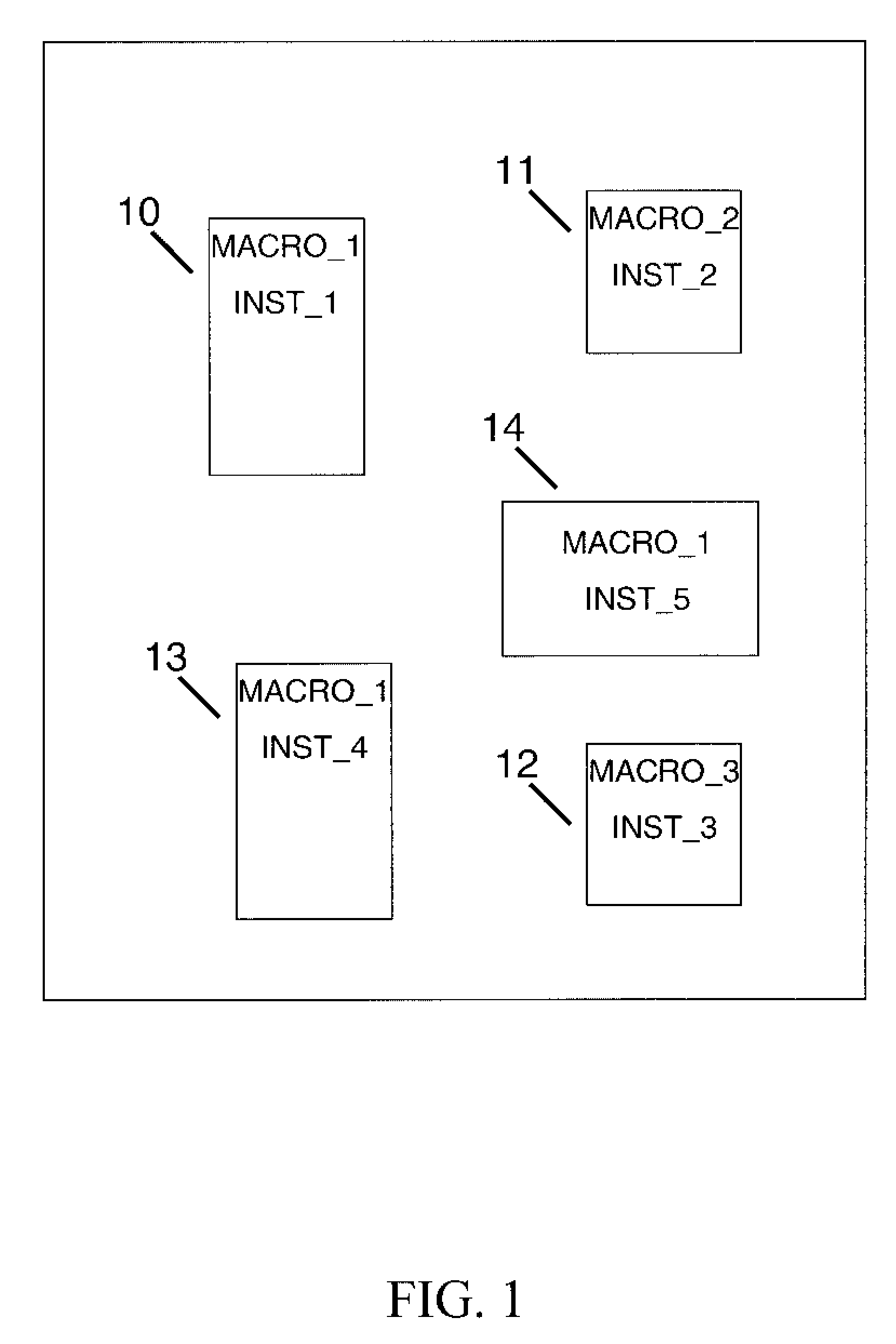
[0029]Turning now to the drawings in greater detail, it will be seen that FIG. 1 depicts a typical physical design structure comprising a plurality of physical entities hereafter referred to as macros. These macros defines arbitrary logic structure which typically have a hard physical boundary with absolute dimensions, aspect ratios, wiring layers, and they serve as the lowest level objects in the design hierarchy which participate in floor planning exercises. In FIG. 1, there are 3 unique macros denoted Macro_1 (10), Macro_2 (11) and Macro_3 (12), which exemplify three unique logic design structures. The complexity of the logic structure within a macro is completely arbitrary, so one of said macros could represent something as simple as an Input / Output block while another macro could describe a complex entity such as a memory controller. Each of these macros arc not only unique behavioral blocks, but each macro is instantiated into the design as a unique instance and given the name...


PUM


Abstract

Design Data Management uses one copy of common data sets along with a plurality of instances, while continuing to utilize the existing design databases and existing CAD tools. Allowing a minimum amount of user intervention to create and maintain the common data set, Design Data Management employs replicating common data sets into one or more clone data sets. The method preferred provides for replicating and synchronizing one or more data sets with a master data set, comprises providing data design management of a master data set and at least one clone data set, and copying a master physical design data set into one or more physical instances to enable customization of said one or more physical instances. The master data set describes at least one of: a design component, a circuit macro, and a circuit entity, and comprises logical data sets, and it comprise physical design data sets. This permits all existing verification processes that are normally executed against the common data set to also be equally applied to the clones of said data set by way of automatic synchronization between of the common dataset and the clones.

Description

TRADEMARKS[0001]IBM® is a registered trademark of International Business Machines Corporation, Armonk, N.Y., U.S.A. Other names used herein may be registered trademarks, trademarks or product names of International Business Machines Corporation or other companies.SECTION 1.01 BACKGROUND OF THE INVENTION[0002]1. Field of the Invention[0003]This invention relates in general to an improved method of managing design data for an integrated circuit for computers and digital systems and, in particular, to the management of design data associated with many unique physical copies of one logical entity.[0004]2. Description of Background[0005]The need to customize individual physical copies (known as “instances”) of a particular building block, or macro, for an integrated circuit is becoming more common as the complexity and performance of those circuits increase. These macros can be as simple as a buffer or IO book, or as complex as an entire microprocessor core, as well as anything in betwee...

Claims


Application Information

Patent Timeline
Patent Type & Authority Patents(United States)
IPC IPC(8): G06F17/50
CPCG06F17/30575G06F11/2094G06F16/27
Inventor VAN HUBEN, GARY A.WEBBER, DAVID A.BERRY, CHRISTOPHER J.
Owner IBM CORP
Why Eureka
Try Eureka