Illuminated face receptacle structure

a face and receptacle technology, applied in the direction of coupling device connection, lighting and heating apparatus, instruments, etc., can solve the problems of electrical connectivity breakage, fire, shock or electrocution, certain types of faults known to occur in branch electric circuits and electrical wiring systems, etc., and achieve the effect of convenient location

Inactive Publication Date: 2010-06-15
PASS SEYMOUR
View PDF14 Cites 34 Cited by
  • Summary
  • Abstract
  • Description
  • Claims
  • Application Information

AI Technical Summary

Benefits of technology

[0013]The present invention addresses the needs described above by providing an aesthetically pleasing illuminated receptacle outlet that may be easily located within a darkened room or area. The wiring device of the present invention is configured to direct illumination into the receptacle openings without forming a hot spot, allowing the user to align the plug blades with the receptacle openings without any additional ambient lighting. The present invention also is directed to an illuminated wiring device that indicates, at a glance, whether or not the device is energized or deenergized.

Problems solved by technology

Certain types of faults are known to occur in branch electric circuits and electrical wiring systems.
These faults represent serious safety issues that may result in fire, shock or electrocution if not addressed properly.
The circuit interrupter provides power to the load terminals under normal conditions, but breaks electrical connectivity when the protective device detects a fault condition in the load circuit.
One issue that is of great concern relates to the visibility of a GFCI or receptacle outlet.
Electrical outlets are often disposed a little more than a foot from the floor in many installations making them difficult to locate when the face cover matches the wall surface.
In other situations, items of furniture or other such things may partially obscure an outlet, again, making it difficult to locate.
Of course, if the space is darkened, the process may not be performed without a good deal of fuss and bother.
In another scenario, an electrical fault condition may occur, tripping a circuit interrupter disposed in either a wall mounted GFCI device or in the breaker panel.
Of course, the tripping action would result in the electrical outlets in the branch circuit being deenergized.
As noted above, some fault conditions may result in fire.
One drawback to this approach relates to the amount and quality of the illumination provided at the receptacle face.
One unintended consequence of this arrangement is that it makes the receptacle openings difficult to find because they are masked by the hot spot.
Of course, hot spots are not aesthetically pleasing and tend to annoy after awhile.

Method used


Image

  • Illuminated face receptacle structure
  • Illuminated face receptacle structure
  • Illuminated face receptacle structure

Examples


first embodiment

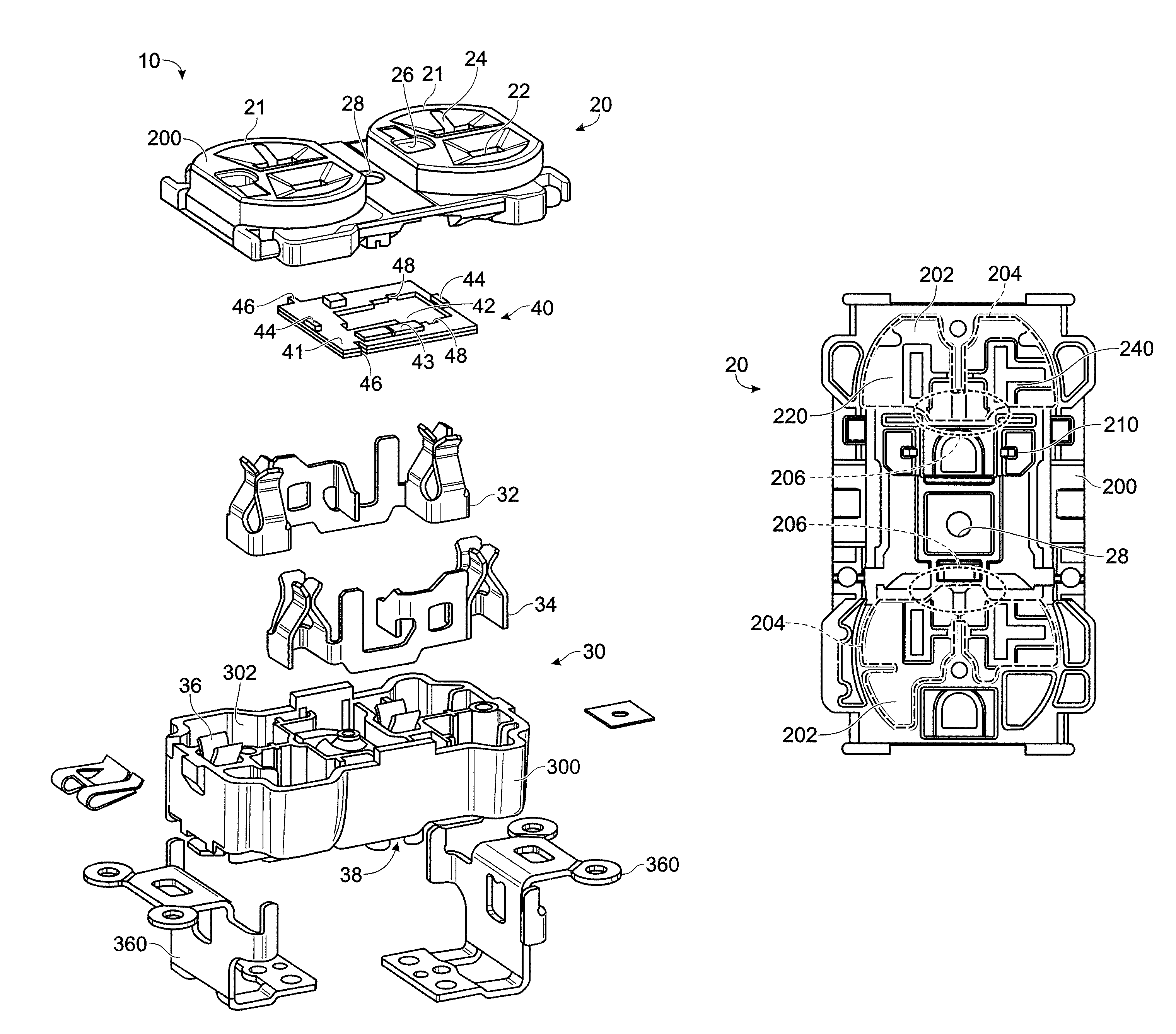
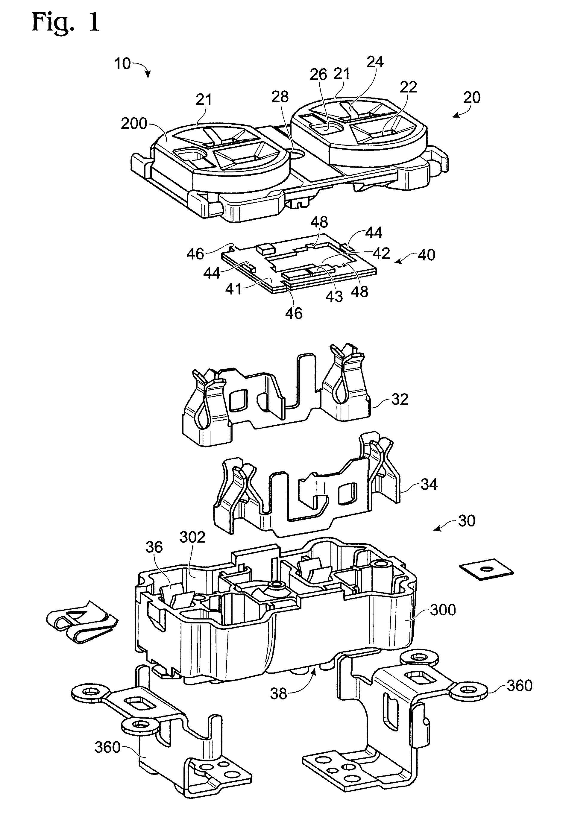
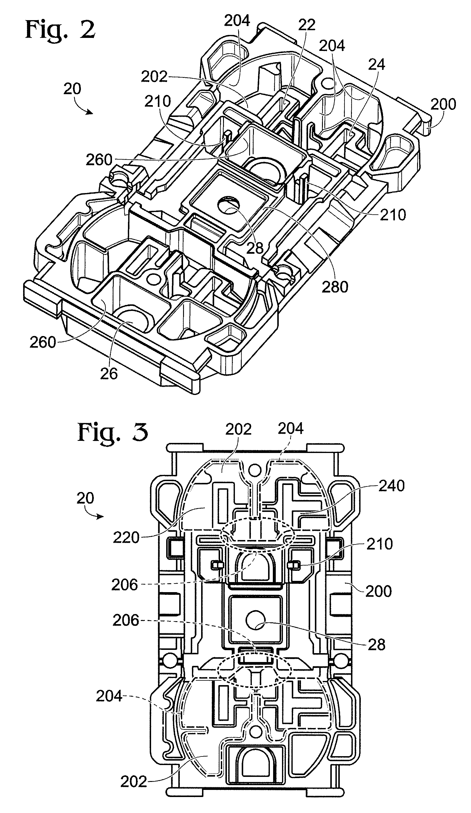
[0034]As embodied herein and depicted in FIG. 1, an exploded perspective view of an electrical wiring system according to the present invention is disclosed. The electrical wiring system 10 includes a front cover assembly 20, a back body assembly 30, and a light assembly 40.

[0035]The front cover assembly 20 includes a front cover member 200 that includes two face receptacles 21 formed at either end. Each face receptacle 21 has a hot blade opening 22, a neutral blade opening 24, and a ground prong openings 26 formed in the substantially planar top surface thereof. A mounting screw hole 28 is disposed between each face receptacle 21. A light assembly 40 is disposed within an interior portion of the front cover assembly 20 in manner described herein.

[0036]The back body assembly 30 includes a body member 300 that has various compartments 302 formed therein. The compartments 302 are formed to accommodate a neutral load terminal structure 32, a hot load terminal structure 34 and a ground ...

third embodiment

[0049]As embodied herein and depicted in FIG. 9, an exploded perspective view of the present invention is disclosed. Like the first two embodiments, the electrical wiring system 10 includes a front cover assembly 20, a back body assembly 30, and a light assembly 40. The front cover assembly 20 is very similar, if not identical, to the previous embodiments, and includes a front cover member 200 that includes two face receptacles 21 formed at either end. Each face receptacle 21 has a hot blade opening 22, a neutral blade opening 24, and a ground prong openings 26 formed therein. A light assembly 40 is disposed within an interior portion of the front cover assembly 20 in manner previously described. The aperture 42 depicted in FIG. 9 is similar to the one shown in FIG. 4.

[0050]The rear body assembly 30 is different from the earlier embodiments. The rear receptacle is replaced by neutral side screw terminals (320, 322), which are not shown in this view, and hot side screw terminals (340...

fourth embodiment

[0051]FIG. 10 is an exploded perspective view of an electrical wiring system according to the present invention. FIG. 10 is almost identical to the embodiment depicted in FIG. 9. The power connection leads 46 employed in FIG. 9 are replaced by power connection clips 460. Further, the aperture 42 depicted in FIG. 10 is similar to the one shown in FIG. 1.

[0052]As embodied herein and depicted in FIGS. 11A to 11C, various top views of printed circuit board (PCB) 41 are disclosed. In each of these embodiments, the configuration of aperture 42 is varied in accordance with the geometry of the cover member 200. In FIG. 11A, aperture 42 includes a first rectangular portion that accommodates the interior ground prong chamber 260 and a second rectangular portion that accommodates the rectangular ribbing 280 that is disposed in the front cover 200 around ground screw opening 28 (See FIG. 2). In FIG. 11B, the second rectangular portion 422 is replaced by a “cul-de-sac” feature comprising circula...


PUM


Abstract

The present invention is directed to an electrical wiring device having a body and a cover coupled to the body including a receptacle face structure which forms an interior region with at least one reflective surface. At least one light emitting device is disposed in the interior region which is configured to emit illumination into at least one neutral opening and a hot opening.

Description

BACKGROUND OF THE INVENTION[0001]1. Field of the Invention[0002]The present invention relates generally to electrical wiring devices, and particularly to illuminated electrical wiring devices.[0003]2. Technical Background[0004]The typical electrical distribution system includes one or more branch electrical circuits connected to a panel breaker disposed at a convenient location in the structure. The breaker panel terminates the AC power service provided by the power utility and distributes AC power to the aforementioned branch electric circuits installed within the structure. The size of the breaker panel may vary depending on whether it is disposed within a residence, commercial building or some other such facility. Branch electric circuits typically include a series of “daisy-chained” electrical wiring devices, such as receptacle outlets, GFCIs, switches, etc.[0005]The electrical wiring devices are provided in electrically non-conductive housings that include hot and neutral line ...

Claims


Application Information

Patent Timeline
Patent Type & Authority Patents(United States)
IPC IPC(8): H01R3/00H01R13/60
CPCF21V33/00H01R24/76H01R13/7175F21Y2101/02H01R2103/00H01R25/006F21Y2115/10
Inventor BHOSALE, VIKRAMSINH P.HAINES, JOSHUA P.
Owner PASS SEYMOUR
Why Eureka
Try Eureka