Photoelectric conversion device and electronic device provided with the photoelectric conversion device
a technology of photoelectric conversion device and electronic device, which is applied in the direction of radiation controlled device, optical radiation measurement, instruments, etc., can solve the problem of not being able to obtain a wide dynamic range, and achieve the effect of widened output voltage range and widened dynamic range of optical sensor
- Summary
- Abstract
- Description
- Claims
- Application Information
AI Technical Summary
Benefits of technology
Problems solved by technology
Method used
Image
Examples
embodiment mode 1
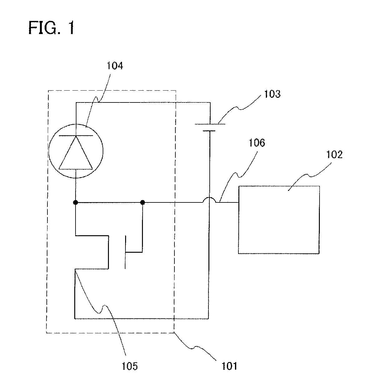
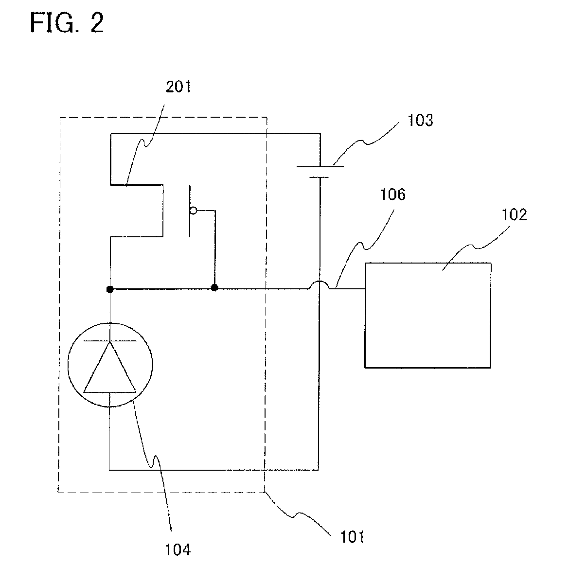
[0035]This embodiment mode will be described with reference to FIG. 1. A photoelectric conversion device shown in FIG. 1 includes a photoelectric conversion circuit 101, a voltage detection circuit 102, and a DC power supply 103. The photoelectric conversion circuit 101 includes a photoelectric conversion element 104 and an n-channel transistor 105. A first terminal (also referred to as an input terminal or a cathode) which is a cathode of the photoelectric conversion element 104 is connected to a high potential terminal (also referred to as a first terminal) of the DC power supply 103. In addition, a second terminal (also referred to as an output terminal or an anode) which is an anode of the photoelectric conversion element 104 is connected to a drain terminal and a gate terminal of the n-channel transistor 105. Note that the second terminal of the photoelectric conversion element 104 is connected to the voltage detection circuit 102 as an output terminal 106 of the photoelectric ...
embodiment mode 2
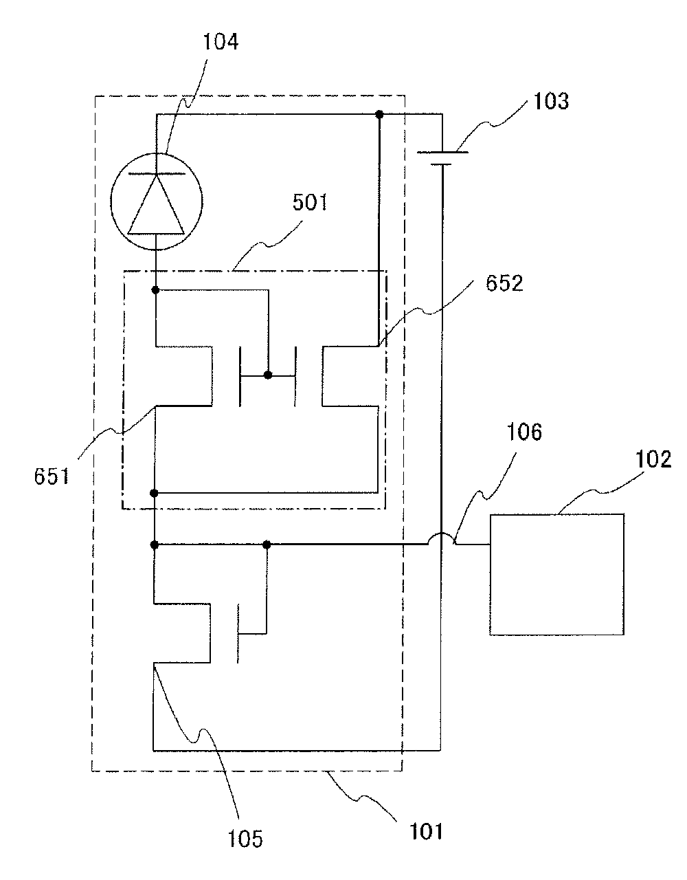
[0063]Embodiment Mode 2 of the present invention, which has a different structure from the photoelectric conversion device described in the above embodiment mode, will be described with reference to FIG. 6. A photoelectric conversion device described in this embodiment mode includes the photoelectric conversion circuit 101, the voltage detection circuit 102, and the DC power supply 103. The difference from the photoelectric conversion circuit described with reference to FIG. 1 in Embodiment Mode 1 is that the photoelectric conversion circuit 101 has a current amplifier 501 between the photoelectric conversion element 104 and the n-channel transistor 105. The first terminal which is a cathode of the photoelectric conversion element 104 is connected to the high potential terminal of the DC power supply 103. The second terminal which is an anode of the photoelectric conversion element 104 is connected to an input terminal of the current amplifier 501. An output terminal of the current ...
embodiment mode 3
[0070]Embodiment Mode 3 of the present invention will be described with reference to FIG. 9. This embodiment mode differs from the photoelectric conversion device of Embodiment Mode 1 in FIG. 1 in that a plurality of the n-channel transistors 105, such as the n-channel transistors 105-1, 105-2, 105-3, to 105-N (N is a natural number), are included in the photoelectric conversion circuit shown in this embodiment mode while one n-channel transistor 105 is included in the photoelectric conversion circuit in FIG. 1.
[0071]The n-channel transistor 105 is a circuit for converting the photocurrent Ip into the output voltage Vout in the photoelectric conversion circuit 101, and the characteristics of the n-channel transistor 105 may vary due to various factors in the manufacturing steps in some cases. Even when the same amount of the photocurrent Ip is input, the level of the output voltage Vout changes due to the variation of the characteristics, and there is a possibility of a problem that...
PUM
 Abstract
Description
Claims
Application Information
 - R&D
- Intellectual Property
- Life Sciences
- Materials
- Tech Scout
- Unparalleled Data Quality
- Higher Quality Content
- 60% Fewer Hallucinations
Browse by: Latest US Patents, China's latest patents, Technical Efficacy Thesaurus, Application Domain, Technology Topic, Popular Technical Reports.
© 2025 PatSnap. All rights reserved.Legal|Privacy policy|Modern Slavery Act Transparency Statement|Sitemap|About US| Contact US: help@patsnap.com


