Semiconductor device, step-down chopper regulator, and electronic equipment

a step-down chopper and step-down technology, applied in the direction of logic circuit coupling/interface arrangement, pulse technique, instruments, etc., can solve the problems of increasing cost, reducing the resistance of switching elements, and lowering power conversion efficiency, so as to achieve stable step-down chopping action, wide input voltage range, and secure boot operation

Inactive Publication Date: 2010-06-15
SHARP KK
View PDF8 Cites 11 Cited by
  • Summary
  • Abstract
  • Description
  • Claims
  • Application Information

AI Technical Summary

Benefits of technology

[0018]An object of the present invention is to provide a semiconductor device for a step-down chopper regulator that has a wide input voltage range and is capable of supporting high-speed oscillation and a secure boot operation with a light load so as to realize a stable step-down chopping action without requiring an expensive process, and to provide a step-down chopper regulator and an electronic equipment that use the semiconductor device.

Problems solved by technology

In the switching power supply, a power loss due to on-resistance of a switching element that increases in proportion to increase of current flowing in the equipment is a main factor that lowers the power conversion efficiency.
Note that the on-resistance of the switching element can be reduced by increasing a size of the switching element, but the increase of size of the switching element must be minimized because it causes increase of cost.
Therefore, it is unnecessary to prepare the output power transistor 100 as a discrete component, but cost of the step-down chopper regulator IC increases.
In addition, a much more expensive process is necessary for making the boot diode 106 as a Schottky barrier diode in order to support high speed oscillation.
It is unable to set exceeding the above-mentioned gate withstand voltage.
However, the above-mentioned conventional constant voltage circuit generates the constant voltage based on the output voltage (the switched voltage having a rectangular waveform) as a reference voltage, so the constant voltage circuit has a very complicated structure.
In this case, the boot capacitor 107 is charged insufficiently so that gate-source voltage of the output power transistor 100 rises insufficiently resulting in malfunction in the switching action.

Method used


Image

  • Semiconductor device, step-down chopper regulator, and electronic equipment
  • Semiconductor device, step-down chopper regulator, and electronic equipment
  • Semiconductor device, step-down chopper regulator, and electronic equipment

Examples


first embodiment

[0041]First, a step-down chopper regulator (a step-down switching regulator) according to the present invention will be described in detail.

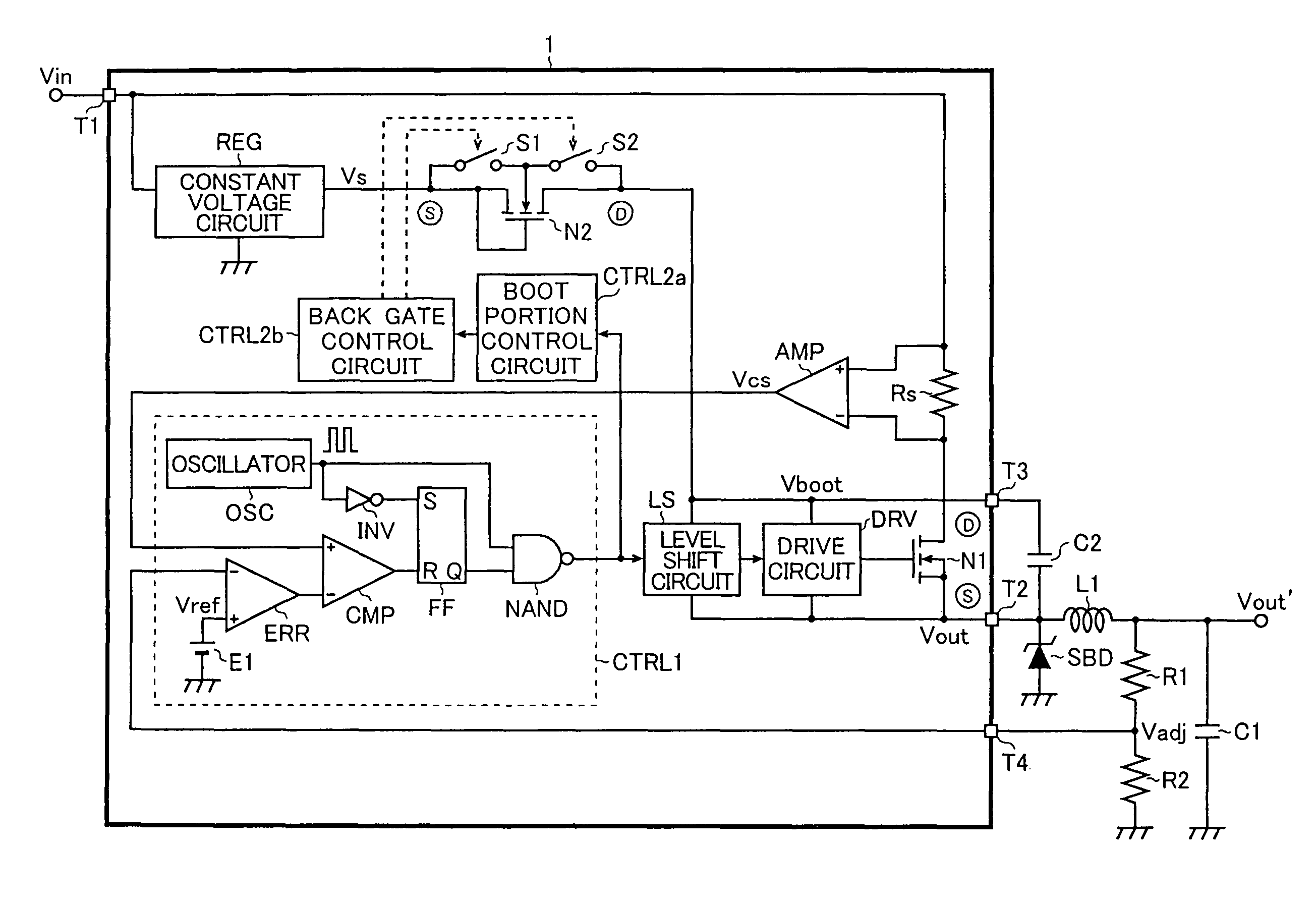
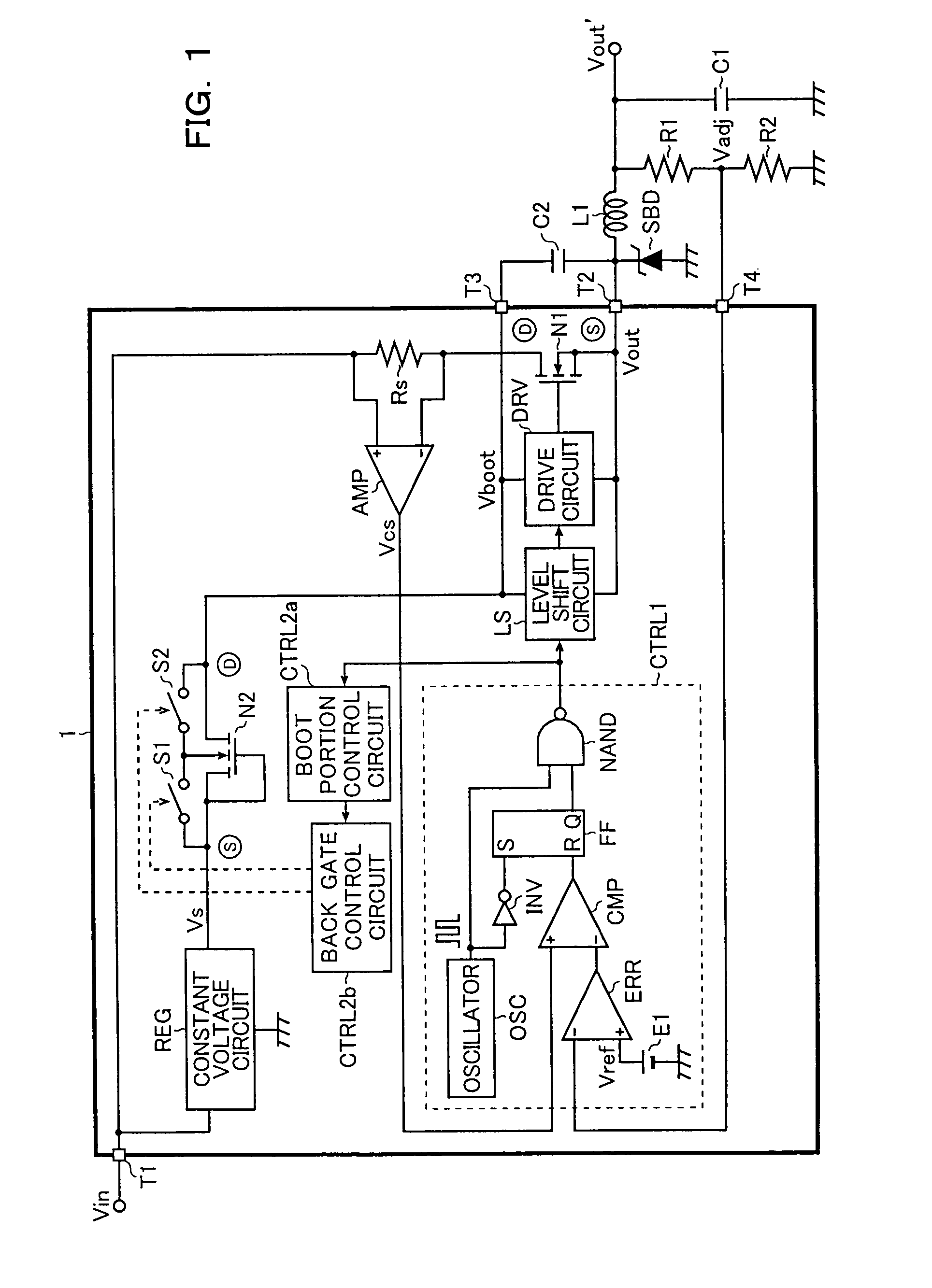
[0042]FIG. 1 is a block diagram showing the first embodiment of the step-down chopper regulator (step-down switching regulator) according to the present invention.

[0043]As shown in FIG. 1, the step-down chopper regulator according to the present invention is made up of a semiconductor device (a step-down chopper regulator IC) 1, an output inductor L1, an output capacitor C1, a Schottky barrier diode SBD, a boot capacitor C2, and resistors R1 and R2. It steps down an input voltage Vin so as to generate a desired smooth output voltage Vout′, which is supplied to a load (not shown) as a drive voltage.

[0044]The semiconductor device 1 is made up of integrated elements including an output power transistor (a N-channel LDMOS transistor) N1, an N-channel LDMOS transistor N2 that is a substitute element of a conventional boot diode (see FIG. 21), a main ...

second embodiment

[0093]Next, the step-down chopper regulator according to the present invention will be described in detail.

[0094]FIG. 10 is a block diagram showing a second embodiment of the step-down chopper regulator according to the present invention.

[0095]Note that the step-down chopper regulator of the present embodiment has substantially the same structure as the first embodiment described above. Therefore, parts similar to the first embodiment are denoted by the same reference signs as those in FIG. 1 so that the descriptions thereof will be omitted. Only the characteristic portions of the present embodiment will be described mainly in the following explanation.

[0096]As shown in FIG. 10, the semiconductor device 1 of the step-down chopper regulator in the present embodiment includes a second constant voltage circuit REG2 that generates a second constant voltage Vs2 (here, the gate withstand voltage of the LDMOS transistor N2) that is higher than the constant voltage Vs from the input voltage...

third embodiment

[0106]Next, the step-down chopper regulator according to the present invention will be described in detail.

[0107]FIG. 12 is a diagram showing a third embodiment of the step-down chopper regulator according to the present invention.

[0108]Note that the step-down chopper regulator of the present embodiment has a structure that is substantially the same as that in the first embodiment. Therefore, parts similar to the first embodiment are denoted by the same reference signs as those in FIG. 1 so that the descriptions thereof will be omitted. Only the characteristic portions of the present embodiment will be described mainly in the following explanation.

[0109]Adding to the structural elements in the first embodiment, the semiconductor device 1 further includes a continuous pulse driving transistor (an N-type LDMOS transistor) N3, a continuous pulse portion control circuit (a second logic generating circuit) CTRL3 and a continuous pulse portion drive circuit (a second drive circuit) DRV2 t...


PUM


Abstract

A bootstrap circuit for a step-down chopper regulator IC includes an LDMOS transistor having a gate and a source connected to output terminals of a constant voltage circuit and a drain connected to a leader terminal of a boot voltage, and a bootstrap control circuit that performs control of turning on and off the LDMOS transistor so as to support high-speed oscillation without requiring expensive process and realize a stable step-down chopping action with a wide input voltage range.

Description

CROSS-REFERENCE TO RELATED APPLICATIONS[0001]This application is based on Japanese Patent Applications No. 2006-235558 and No. 2006-235576 filed on Aug. 31, 2006, the contents of which are hereby incorporated by reference.BACKGROUND OF THE INVENTION[0002]1. Field of the Invention[0003]The present invention relates to a power supply circuit that steps down an input voltage and supplies it to a load. In particular, the present invention relates to a step-down chopper regulator that obtains a drive voltage to be given to a gate of an output power transistor by a bootstrap method.[0004]2. Description of Related Art[0005]Improvement of power conversion efficiency causes effects of energy saving, long life of batteries, reduction of heat and the like, so it is the most important task for a switching power supply. In addition, as a result of recent promotion of energy saving, equipment to be supplied with power from the switching power supply has become to support low voltage, i.e., capabl...

Claims


Application Information

Patent Timeline
Patent Type & Authority Patents(United States)
IPC IPC(8): H02M7/537
CPCH02M3/156H03K2217/0018H03K17/166
Inventor KANAMORI, ATSUSHIWARITA, HIROHISAKIMURA, TADAMASA
Owner SHARP KK
Why Eureka
Try Eureka