Servo channel for tape drive systems

a technology of servo channel and tape drive, which is applied in the direction of data recording, magnetic recording, instruments, etc., can solve the problems of large noise level, increased complexity, and reduced reliability of computed estimates

Active Publication Date: 2010-06-22
TWITTER INC
View PDF8 Cites 21 Cited by
  • Summary
  • Abstract
  • Description
  • Claims
  • Application Information

AI Technical Summary

Problems solved by technology

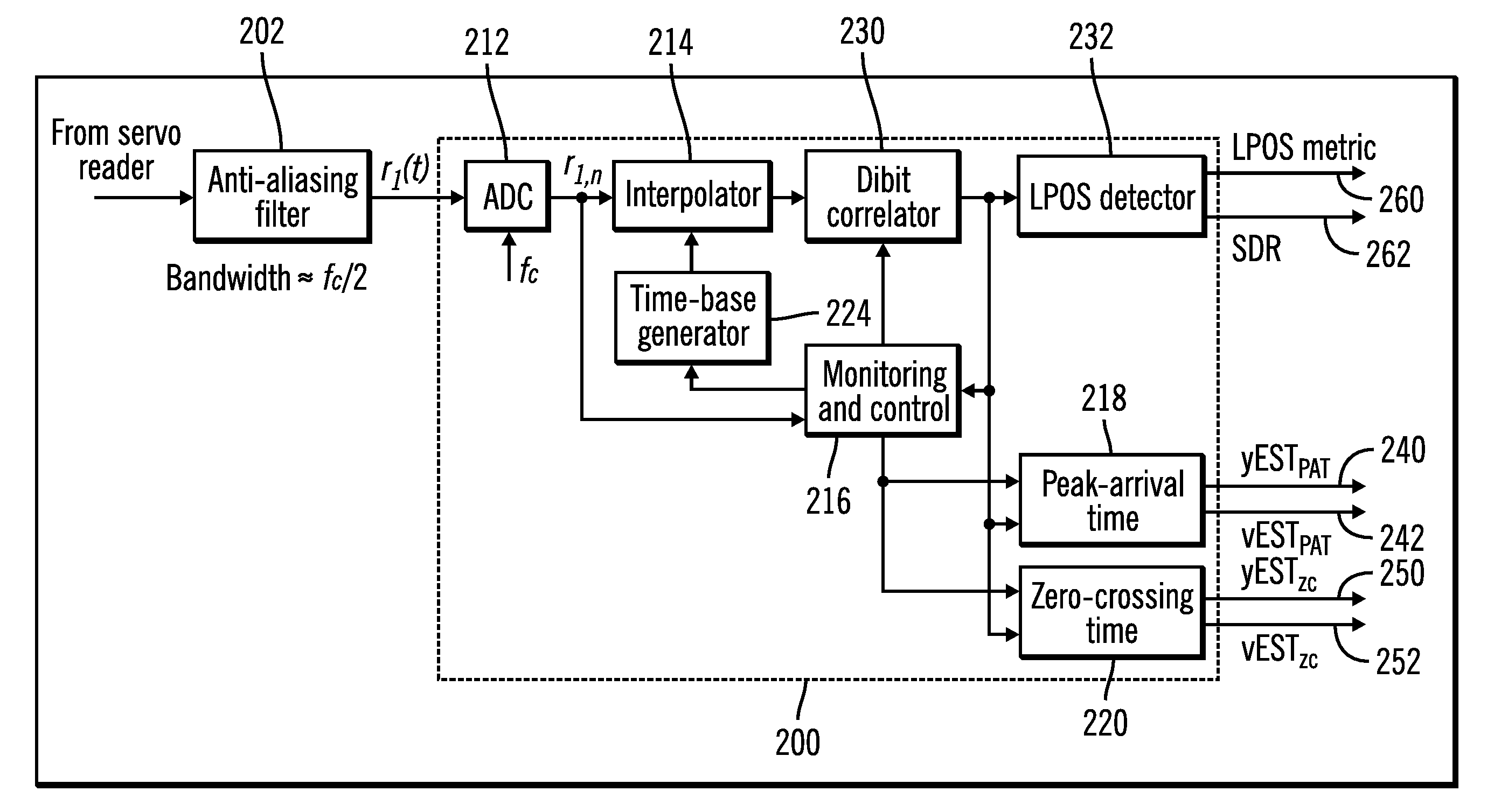
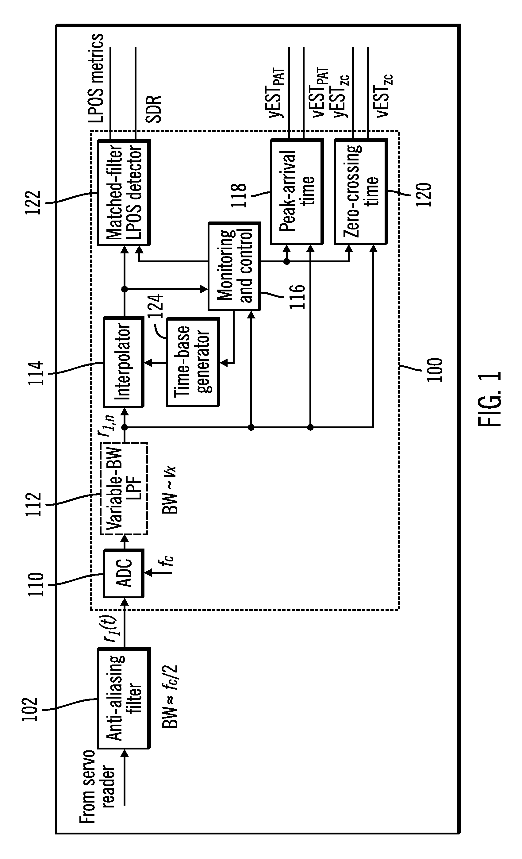
Unfortunately, at low tape velocities a fixed low-pass filter exhibits significant excess bandwidth, which leads to a large noise level, and may greatly reduce the reliability of the computed estimates, depending on the tape velocity.
This approach has the requirement that the bandwidth of the anti-aliasing filter be selectable, which leads to increased complexity.
A further disadvantage arises if the bandwidth of the servo reader signal for the minimum cruise velocity of the tape is significantly smaller than the minimum available clock frequency of the ADC.
In this case, which is found in practice, excess noise bandwidth cannot be eliminated at low tape velocities.
Another drawback of this approach is that a variable clock rate would be required during tape acceleration and deceleration to guarantee minimum-bandwidth filtering.
Such a solution, however, leads to a significant increase in the complexity of the implementation of the servo channel.

Method used


Image

  • Servo channel for tape drive systems
  • Servo channel for tape drive systems
  • Servo channel for tape drive systems

Examples


embodiment details

ADDITIONAL EMBODIMENT DETAILS

[0058]The described operations may be implemented as a method, computer program product or apparatus using standard programming and / or engineering techniques to produce software, firmware, hardware, or any combination thereof.

[0059]Each of the embodiments may take the form of an entirely hardware embodiment, an entirely software embodiment or an embodiment containing both hardware and software elements. The embodiments may be implemented in software, which includes but is not limited to firmware, resident software, microcode, etc.

[0060]Furthermore, the embodiments may take the form of a computer program product accessible from a computer-usable or computer-readable medium providing program code for use by or in connection with a computer or any instruction execution system. For the purposes of this description, a computer-usable or computer readable medium may be any apparatus that may contain, store, communicate, propagate, or transport the program for ...


PUM

PropertyMeasurementUnit
accelerationaaaaaaaaaa
widthaaaaaaaaaa
velocityaaaaaaaaaa

Abstract

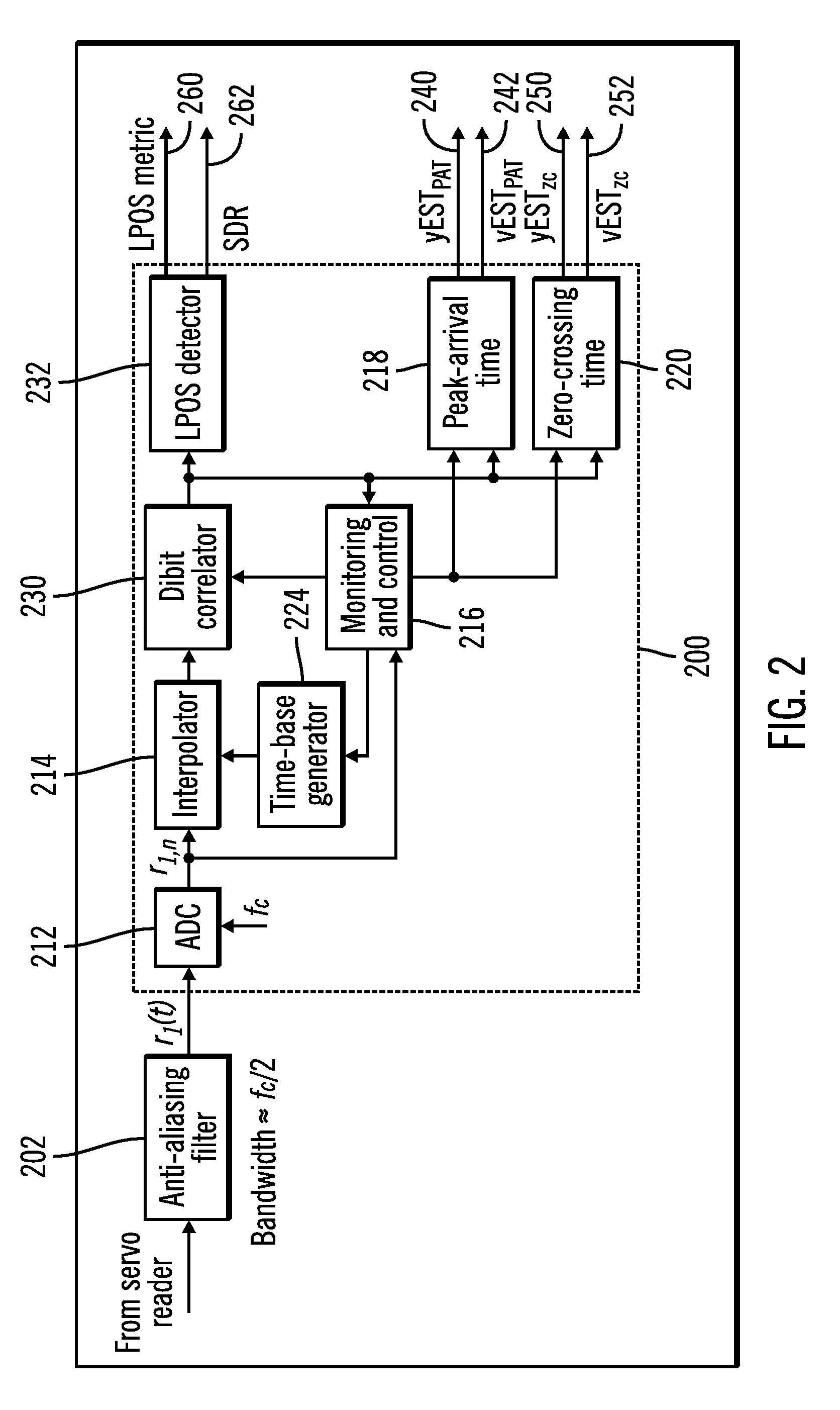
Provided are techniques for synchronous servo channel for a data tape drive. A servo reader is configured to read servo bursts from a data tape. An anti-aliasing filter is operable to output a bandlimited signal and is coupled to receive a servo channel signal comprising servo bursts from the servo reader. An analog-to-digital converter (ADC) is operable to output signal samples and is coupled to receive the bandlimited signal from the anti-aliasing filter. An interpolation and control unit is operable to output interpolated signal samples and control signals, has a first input coupled to receive the signal samples from the ADC, and has a second input coupled to receive the correlation signal samples from the dibit correlator. A dibit correlator is operable to output correlation signal samples and is coupled to receive the interpolated signal samples and control signals from the interpolation and control unit.

Description

BACKGROUND[0001]1. Field[0002]Embodiments of the invention relate to a servo channel for tape drive systems.[0003]2. Description of the Related Art[0004]In timing-based servo (TBS) systems, recorded servo patterns consist of magnetic transitions with two different azimuthal slopes. Head position is derived from the relative timing of pulses, or dibits, generated by a narrow head reading the servo patterns. TBS patterns also allow the encoding of additional longitudinal position (LPOS) information without affecting the generation of the transversal position error signal (PES). This is obtained by shifting transitions from their nominal pattern position using pulse-position modulation (PPM). A specification for the servo format in current tape drives is provided by the linear tape-open (LTO) format. The complete format for LTO drives of generation 1 (LTO-1) was standardized by the European Computer Manufacturers Association (ECMA) in 2001 as ECMA-319. Additional information on LTO tec...

Claims


Application Information

Patent Timeline
Patent Type & Authority Patents(United States)
IPC IPC(8): G11B5/584
CPCG11B5/584
Inventor CHERUBINI, GIOVANNICIDECIYAN, ROY DARONELEFTHERIOU, EVANGELOS S.HUTCHINS, ROBERT ALLENJELITTO, JENS
Owner TWITTER INC
Why Eureka
Try Eureka