Coordinated environment for classification and control of network traffic

a network traffic and environment technology, applied in the field of computer networks, can solve the problems of reducing the efficiency and performance of network devices, affecting the very purpose of network devices deployed, and most cpu-intensive tasks performed, so as to reduce resource requirements, reduce cpu utilization, and increase the efficiency and performance of network traffic classification.

Inactive Publication Date: 2010-06-22
CA TECH INC
View PDF14 Cites 329 Cited by
  • Summary
  • Abstract
  • Description
  • Claims
  • Application Information

AI Technical Summary

Benefits of technology

[0036]In light of the foregoing, a need in the art exists for increasing the efficiency and performance of network traffic classification. A need also exists in the art for reducing the resource requirements associated with network traffic classification. Embodiments of the present invention substantially fulfill these needs.
[0037]The present invention provides methods, apparatuses and systems directed to the coordinated classification of network traffic. In one implementation, the present invention enables a coordinated network environment for traffic classification where an upstream network device classifies a data flow and adds traffic class information to at least one packet in the data flow. Downstream network devices in the communications path to the destination host can use the traffic class information in the modified packet, bypassing at least some of the local traffic classification operations and thereby reducing CPU utilization. In one implementation, the last downstream network device strips the traffic classification information from the modified packet before it is forwarded to the destination host.

Problems solved by technology

If a network device, such as an application traffic management device, becomes a bottleneck, it can defeat the very purpose for which the network device was deployed—namely, increased efficiency and performance.
Classification of data flows especially in modern network environments, however, is often one of the most CPU-intensive tasks performed by the network devices.
In addition, recent trends seen in many network applications suggest that the resource intensive nature of network traffic classification will only increase.
Indeed, data encryption addresses the concern of security and privacy issues, but also makes it much more difficult for intermediate network devices to identify the applications that employ them.
In addition, traffic classification based solely on well-known port numbers can be problematic, especially where a network application uses dynamic port number assignments or incorrectly uses a well-known port number, leading to misclassification of the data flows.
In addition, classifying such encrypted network traffic as unknown (or encrypted) and applying a particular rate or admission policy to unknown traffic classes undermines the granular control otherwise provided by bandwidth management devices and, further, may cause legitimate, encrypted traffic to suffer as a result.
These classification mechanisms differ from traditional classification mechanisms which classify traffic based on explicitly presented attributes of individual data packets; however, they are quite resource intensive, requiring maintenance and analysis of a significant amount of stateful information for each data flow.
While the prior art is suitable for its intended objective, the separate classification of data flows traversing a plurality of identical or similar network devices results in certain inefficiencies.
In other words, a downstream network device, such as bandwidth management device, located along a communications path traversed by a given data flow fails to take advantage of the classification information derived by an upstream network device in the communications path.
The resources spent classifying the traffic reduces performance, which can become a concern as traffic loads increase.

Method used


Image

  • Coordinated environment for classification and control of network traffic
  • Coordinated environment for classification and control of network traffic
  • Coordinated environment for classification and control of network traffic

Examples


Embodiment Construction

)

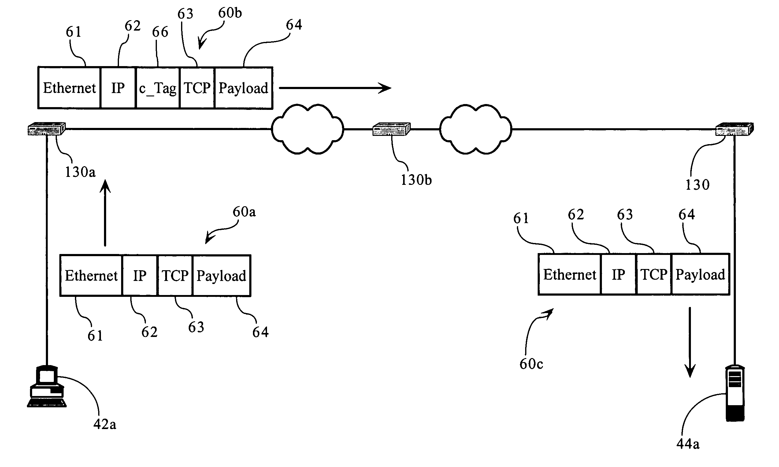
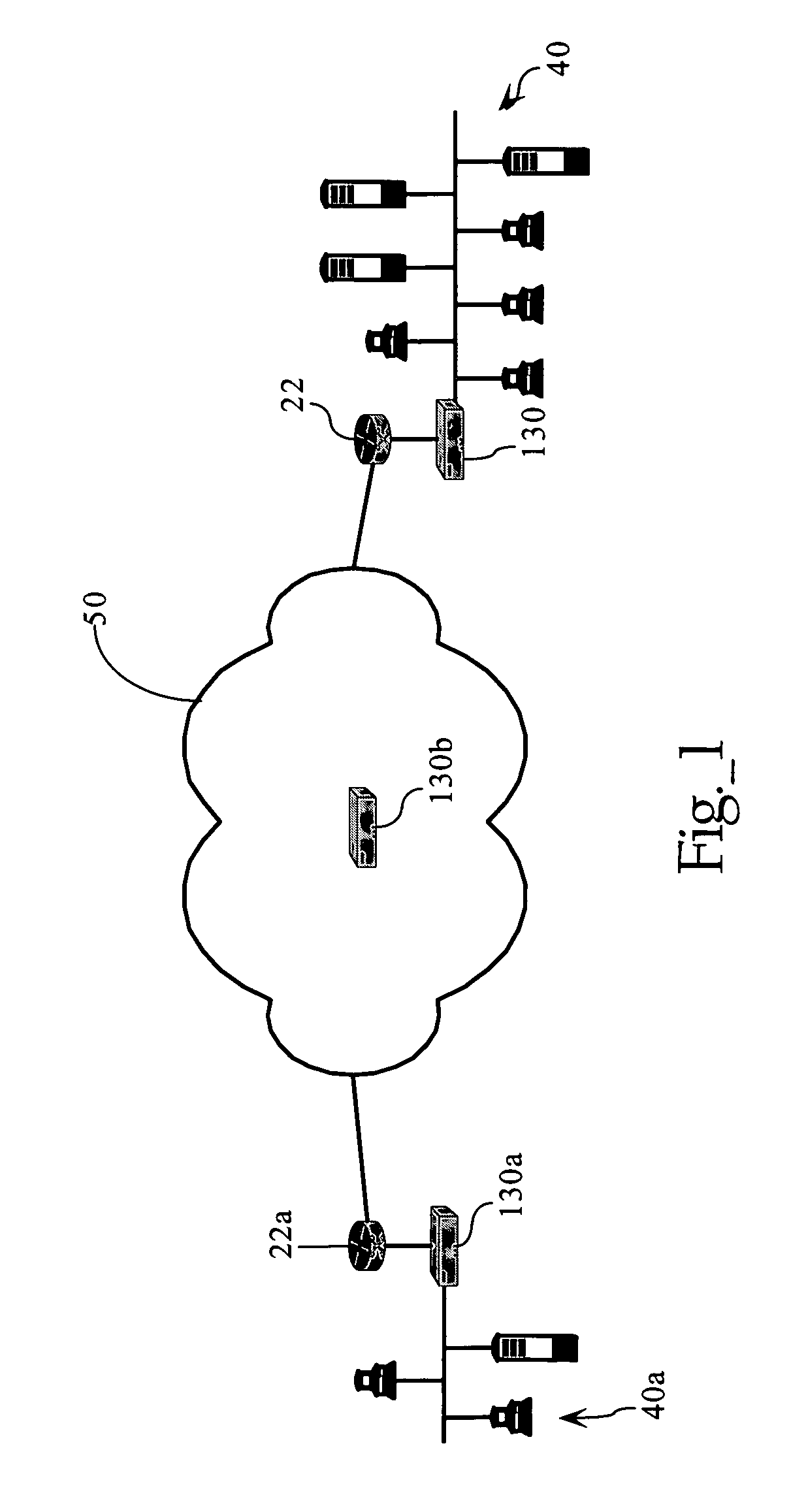
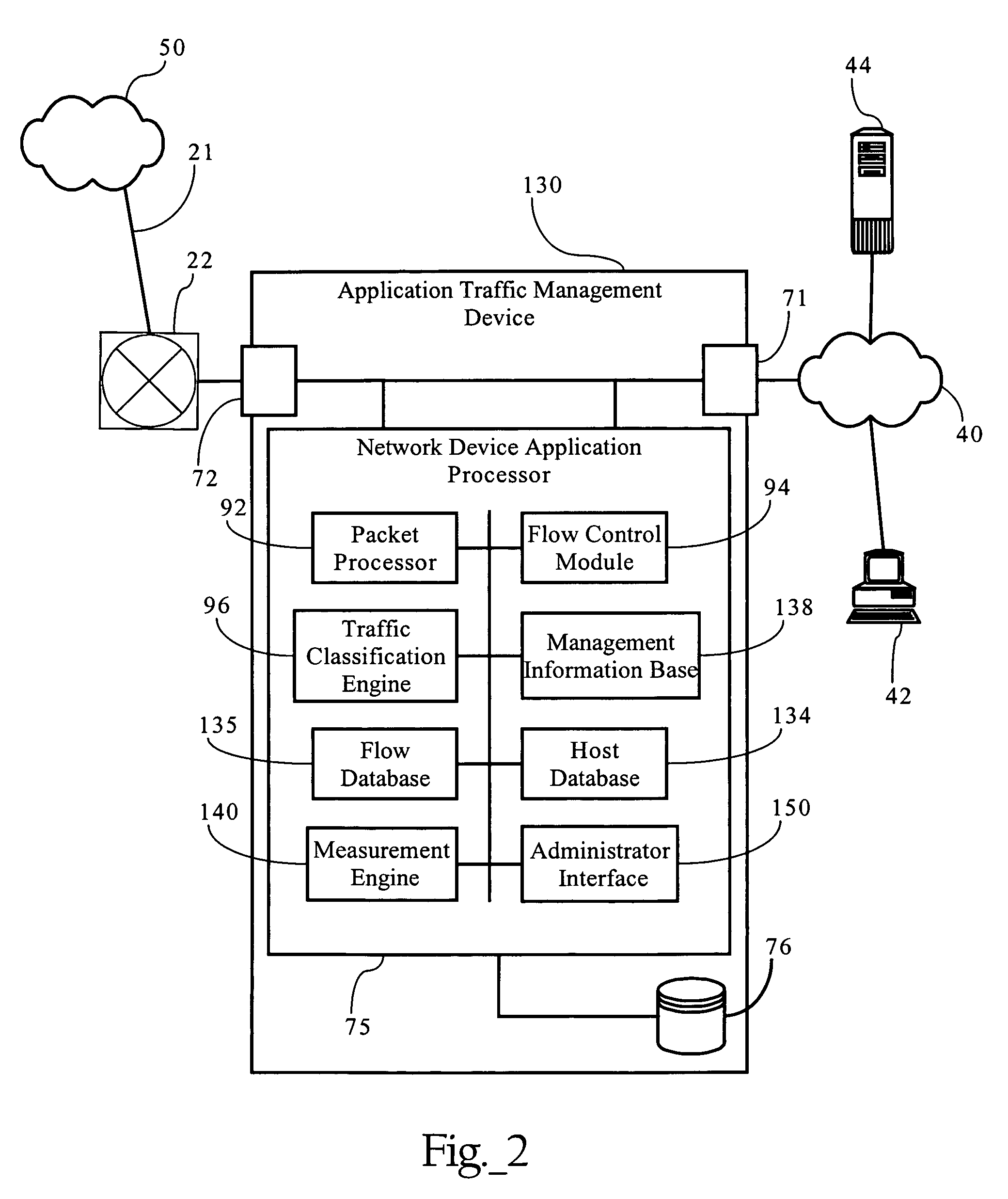
[0044]FIGS. 1 and 2 illustrate an exemplary network environment in which an embodiment of the present invention operates. Of course, the present invention can be applied to a variety of network architectures. FIG. 1 illustrates, for didactic purposes, a network 50, such as wide area network, interconnecting a first enterprise network 40, supporting a central operating or headquarters facility, and a second enterprise network 40a, supporting a branch office facility. As FIG. 2 shows, the first network 40 interconnects several TCP / IP end systems, including client devices 42 and server device 44, and provides access to resources operably connected to computer network 50 via router 22 and access link 21. Access link 21 is a physical and / or logical connection between two networks, such as computer network 50 and network 40. The computer network environment, including network 40 and network 50 is a packet-based communications environment, employing TCP / IP protocols, and / or other suitable...


PUM


Abstract

Methods, apparatuses and systems directed to the coordinated classification of network traffic. In one implementation, the present invention enables a coordinated network environment for traffic classification where an upstream network device classifies a data flow and adds traffic class information to at least one packet in the data flow. Downstream network devices in the communications path to the destination host can use the traffic class information in the modified packet, bypassing at least some of the local traffic classification operations and thereby reducing CPU utilization. In one implementation, the last downstream network device strips the traffic classification information from the modified packet before it is forwarded to the destination host. Embodiments of the invention reduce or eliminate redundant network traffic classification operations performed by a plurality of network devices in a communications path.

Description

CROSS-REFERENCE TO RELATED APPLICATIONS AND PATENTS[0001]This application makes reference to the following commonly owned U.S. patent applications and patents, which are incorporated herein by reference in their entirety for all purposes:[0002]U.S. patent application Ser. No. 08 / 762,828 now U.S. Pat. No. 5,802,106 in the name of Robert L. Packer, entitled “Method for Rapid Data Rate Detection in a Packet Communication Environment Without Data Rate Supervision;”[0003]U.S. patent application Ser. No. 08 / 970,693 now U.S. Pat. No. 6,018,516, in the name of Robert L. Packer, entitled “Method for Minimizing Unneeded Retransmission of Packets in a Packet Communication Environment Supporting a Plurality of Data Link Rates;”[0004]U.S. patent application Ser. No. 08 / 742,994 now U.S. Pat. No. 6,038,216, in the name of Robert L. Packer, entitled “Method for Explicit Data Rate Control in a Packet Communication Environment without Data Rate Supervision;”[0005]U.S. patent application Ser. No. 09 / 9...

Claims


Application Information

Patent Timeline
Patent Type & Authority Patents(United States)
IPC IPC(8): H04L12/26H04L12/28H04L12/56
CPCH04L41/5022H04L47/2441H04L47/10H04L43/0876
Inventor MUPPALA, SURESH
Owner CA TECH INC
Why Eureka
Try Eureka