System and method for dynamometer testing of motor vehicles, including a cooling device

a technology for dynamometers and motor vehicles, applied in the direction of liquid fuel engines, instruments, structural/machine measurement, etc., can solve the problems of difficult cooling of heat generated by power-absorbing means when testing these engines, and achieve the effect of more efficient cooling of generated hea

Active Publication Date: 2010-06-29
ROTOTEST INT
View PDF6 Cites 12 Cited by
  • Summary
  • Abstract
  • Description
  • Claims
  • Application Information

AI Technical Summary

Benefits of technology

[0007]It is an object of the present invention to provide a system for dynamometer testing of motor vehicles including a cooling device that solves the above mentioned problem. In particular, it is an object of the present invention to provide a system that allows more efficient cooling of generated heat in power-absorbing means and / or power-generating means.

Problems solved by technology

A problem with this device, however, is that as vehicle engines increasingly tend to generate higher and higher powers, and higher and higher torques, the heat generated by the power-absorbing means when testing these engines, e.g., as a temperature rise of the hydraulic fluid when passing through the control valve, becomes more difficult to cool.

Method used


Image

  • System and method for dynamometer testing of motor vehicles, including a cooling device
  • System and method for dynamometer testing of motor vehicles, including a cooling device
  • System and method for dynamometer testing of motor vehicles, including a cooling device

Examples


Embodiment Construction

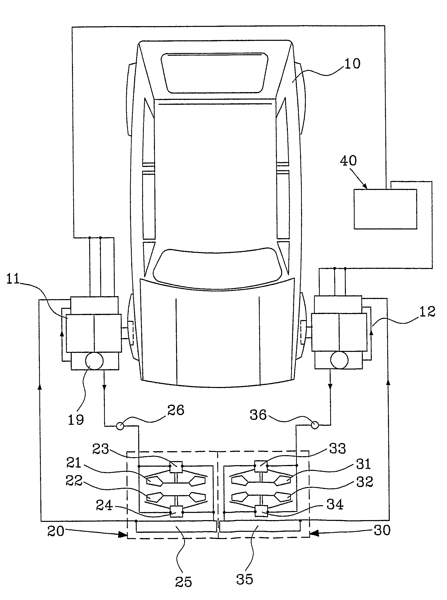
[0024]FIG. 1 shows a dynamometer testing system in which the present invention advantageously may be utilised. The system is connected to a vehicle 10, and comprises a pair of test units 11, 12. Each test unit 11, 12 is connected to a cooling device 20, 30. Each cooling device 20, 30 includes cooling fans 21, 22 (31, 32) which are hydraulically driven by hydraulic motors 23, 24 (33, 34). The two test units 11, 12 and the respective associated cooling devices 20, 30 are connected to a common measuring and control system 40.

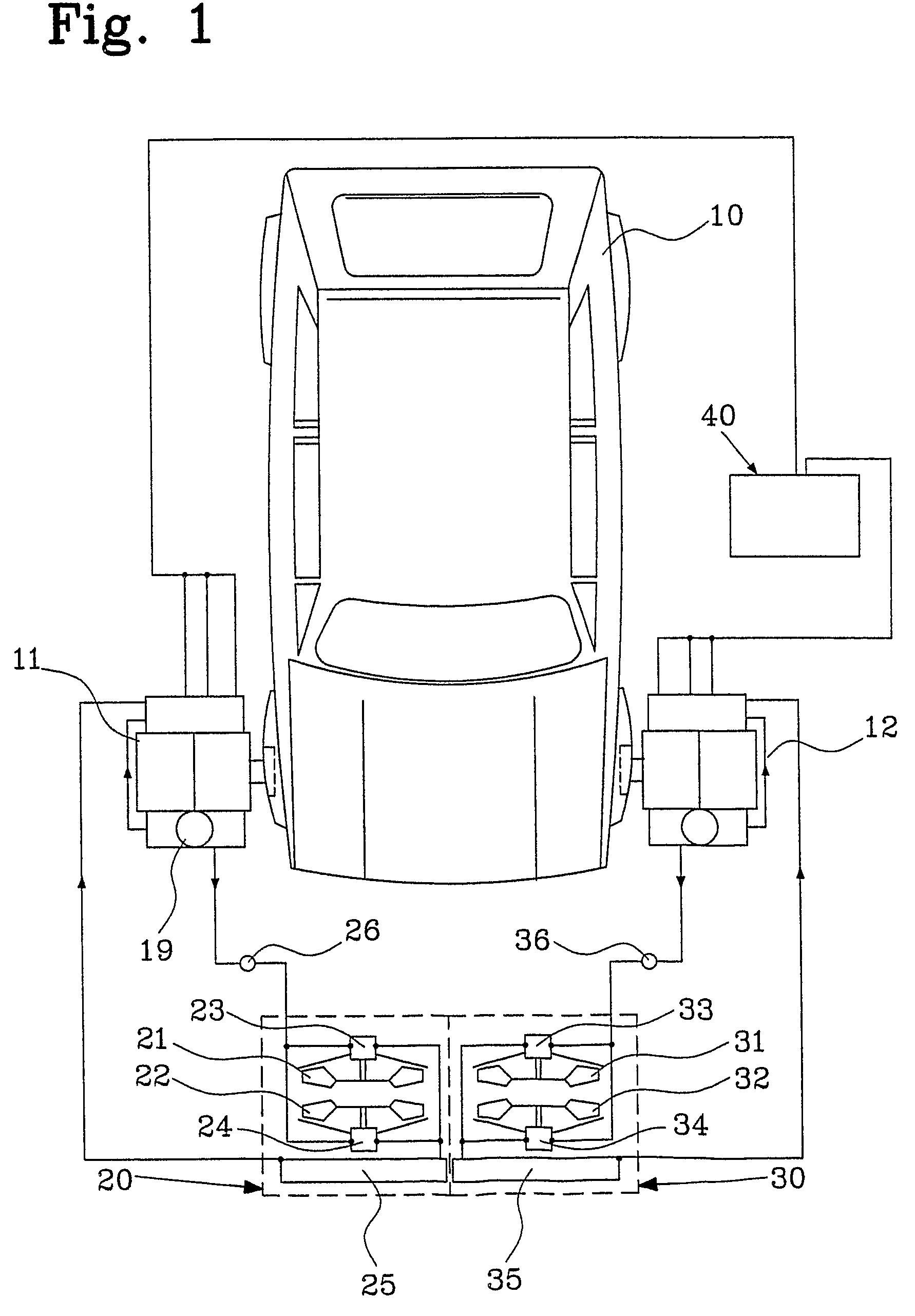
[0025]The test units 11, 12 are similar, and so is the cooling devices 20, 30, and as can be seen more in detail in FIG. 2, which shows the test unit 11 and the cooling device 20, each test unit 11, 12 comprises a dynamometer in the form of a power-absorbing hydrostatic pump assembly, consisting of two commonly driven hydraulic pumps 13, 14 and means for measuring the torque applied to the pump input shaft 15, which is arranged to be rigidly connected to a drive sh...


PUM


Abstract

The present invention relates to a system for dynamometer testing of motor vehicles. The system includes a cooling device for cooling a braking device and / or a power-generating arrangement, such as the engine of a car. The system is arranged to, using the braking device, absorb power applied thereto by the power-generating arrangement. The cooling device includes a fan arrangement for producing an air stream, the air stream being intended to be directed towards the braking device and / or the power-generating arrangement and / or a heat exchanger for providing a cooling effect. The fan arrangement includes two substantially axially aligned fans, and the cooling device is arranged to rotate the fans in opposite directions relative to each other. The present invention also relates to a method.

Description

[0001]This is a national stage of International Application No. PCT / SE2006 / 000639 filed on May 31, 2006 and published in English.FIELD OF THE INVENTION[0002]The present invention relates to a system for dynamometer testing of motor vehicles, said system including a cooling device intended for cooling a braking device and / or power generating means, in particular, a system for dynamometer testing of motor vehicles, including a cooling device for a braking device and / or a power-generating means, and having power-absorbing means for absorbing a power applied thereto by power-generating means, the cooling device including a fan arrangement for producing an air stream, said air stream being intended to provide a cooling effect.[0003]The invention further relates to a method for cooling a braking device and / or a power-generating means in a system for dynamometer testing of motor vehicles, in particular, a method for cooling a braking device and / or a power-generating means in a system for d...

Claims


Application Information

Patent Timeline
Patent Type & Authority Patents(United States)
IPC IPC(8): G01M17/007
CPCF04D19/007G01M17/0072F04D29/582F04D19/024
Inventor ENGSTROM, NILS G
Owner ROTOTEST INT
Why Eureka
Try Eureka