Oscillating-foil type underwater propulsor with a joint

a technology of underwater propulsor and joint, which is applied in the field of underwater propulsor, can solve the problems of inferior device for lifting and taking load, inability to take or transmit a larger thrust, and early flow separation and stall, so as to improve the propulsion efficiency and maneuverability of the propulsor

Inactive Publication Date: 2010-06-29
CHANG JUNG CHRISTIAN UNIV
View PDF6 Cites 6 Cited by
  • Summary
  • Abstract
  • Description
  • Claims
  • Application Information

AI Technical Summary

Benefits of technology

[0008]The invention relates to an oscillating-foil type underwater propulsor with a joint. The underwater propulsor of the invention mimics the tail movement of fast moving cetaceans or tunas and improves the propulsion efficiency and maneuverability of the propulsor, the propulsor being a general-use underwater propulsion device that can be used on a human body, a yacht or a cargo ship.
[0009]According to one embodiment of the invention, an oscillating-foil type underwater propulsor with a joint is provided, the propulsor including a streamline foil having a foil surface being parallel to a water surface and a span length of at least twice as long as an average chord length of the streamline foil; and a heaving mechanism undergoing heaving motion perpendicular to the direction of the span and a propulsion direction of the propulsor and having a transmission section, wherein the transmission section is pivotally connected to the streamline foil to form a joint, the joint being provided at the middle of the span length of the streamline foil and having a rotation center located within a circular area, which has a radius of one third of the average chord length and is centered at the point one third of the average chord length ahead of the lifting center of the streamline foil. The heaving mechanism includes a rotational cylinder being hollow inside and having an opening at the bottom, the rotational cylinder being configured as a body of the heaving mechanism; a first permanent magnet provided around the top of the inside of the rotational cylinder; a second permanent magnet provided around the bottom of the inside of the rotational cylinder; a coil provided around the inside of the rotational cylinder and between the first permanent magnet and the second permanent magnet; and a third permanent magnet provided inside the coil and having a bottom attached to the transmission section. The coil can have an electric current passing through it to induce a magnetic field, the direction of the magnetic field is alternated by alternating the direction of the electric current to enable the third permanent magnet to undergo reciprocal heaving motion so as to actuate the transmission section. In addition, the heaving mechanism further includes a plurality of rollers provided inside the rotational cylinder between the opening and the second permanent magnet to facilitate reciprocal heaving motion of the transmission section. Furthermore, the transmission section has an upper limiter and a lower limiter located on the surface of the end that is pivotally connected to the streamline foil, the upper limiter being configured for limiting counterclockwise rotation of the streamline foil and the lower limiter being configured for limiting clockwise rotation of the streamline foil so that the streamline foil rotates within an angle between about +30 degrees and about −30 degrees. Each of the upper limiter and the lower limiter can have a buffer pad for reducing impact on the transmission section caused by heaving motion of the streamline foil. Moreover, the propulsor of the embodiment further includes a turntable provided on the outside of the rotational cylinder, and a support for supporting the turntable, the support having at least one track. The turntable is engaged with the at least one track to allow the propulsor to rotate 360 degrees so as to change the propulsion direction.
[0011]According to yet another embodiment of the invention, an oscillating-foil type underwater propulsor with a joint for a man-powered watercraft is provided, the propulsor including a streamline foil having a foil surface being parallel to a water surface and a span length of at least twice as long as an average chord length of the streamline foil; a transmission rod having a grip on its top; and a holder being hollow inside and holding the transmission rod in it, wherein the transmission rod is pivotally connected to the streamline foil to form a joint, the joint being provided at the middle of the span length of the streamline foil and having a rotation center located within a circular area, which has a radius of one third of the average chord length and is centered at the point one third of the average chord length ahead of the lifting center of the streamline foil. The propulsor of the embodiment further includes an upper stopper provided at the bottom of the grip to limit downward movement of the transmission rod, and a lower stopper provided on the transmission rod below the holder to limit upward movement of the transmission rod so as to prevent the streamline foil from hitting the hull of the watercraft. In addition, the transmission rod is capable of rotating 360 degrees so as to change the propulsion direction.

Problems solved by technology

For a flat structure such as the flipper, the flat structure can easily cause early flow separation and stall when used as a propulsor in a fluid medium because it does not have a thicker foil thickness and a larger curvature radius of the leading edge of a high performance streamline foil, making it an inferior device for providing lift and taking load.
Besides, the flipper also is a soft or non-rigid structure, which is prone to deformation and unable to take or transmit a larger thrust.
Therefore, the flipper produces a very limited thrust in practical use.
During the rotation of the fins, however, water surrounding the fins travels in a circumferential direction, which is almost helpless in facilitating the propulsion of the ship and becomes energy loss.
For a conventional screw propeller, this problem has been a major barrier to further significant improvement of propulsion efficiency.
Furthermore, the screw propeller has another disadvantage, which is low maneuverability.
When the mechanical power of the marine main engine is transferred to the propeller through the shaft fixed to the hull of the ship, the direction of the thrust produced by the propeller may not be controlled due to the fixed-positioned shaft.
Therefore, the propeller by itself can only produce forward and backward thrusts but not side thrusts.
However, the rudder is only functional when the ship is going forward or backward, and that the side thrust is only a small fraction of the total thrust produced by the propeller, thus the ship can not be flexibly handled to move in the desired direction.
However, the propulsion method of the podded propulsor is the same as that of the propeller in that both types of propulsors use rotating blades and thus cause rotational kinetic energy loss.

Method used


Image

  • Oscillating-foil type underwater propulsor with a joint
  • Oscillating-foil type underwater propulsor with a joint
  • Oscillating-foil type underwater propulsor with a joint

Examples


Embodiment Construction

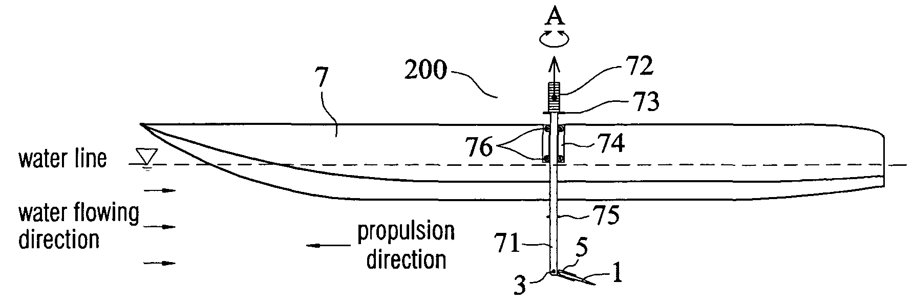
[0029]To increase the propulsion efficiency and maneuverability of a moving underwater object or a floating body, the invention has the following improvements.

1. Underwater Propulsion by Use of an Oscillating Foil

[0030]The invention provides a streamline foil undergoing heaving motion and pitch variation to mimic tail movement of a cetacean swimming at high speed. The oscillating foil pushes water backwards to gain a forward thrust. Thus, propelling in this way avoids rotational energy loss associated with rotating motion of a conventional screw propeller. This type of propulsion has a higher propulsion efficiency than that of a screw propeller.

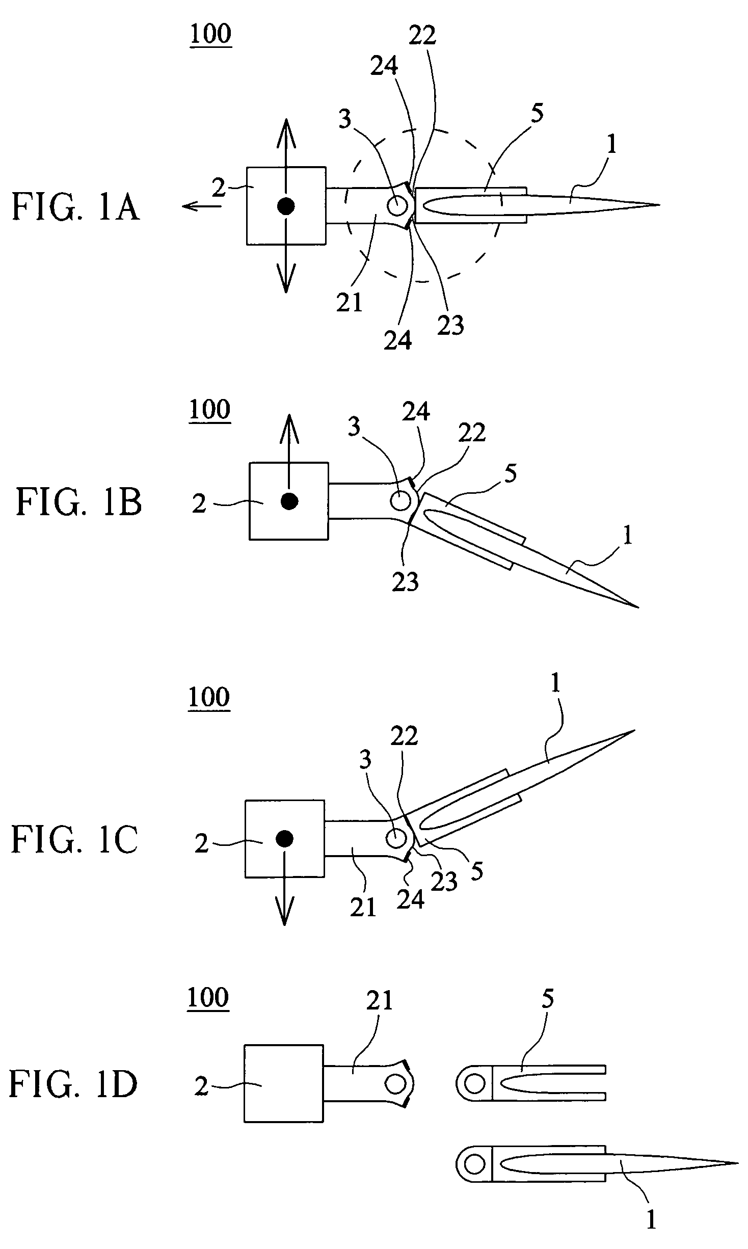
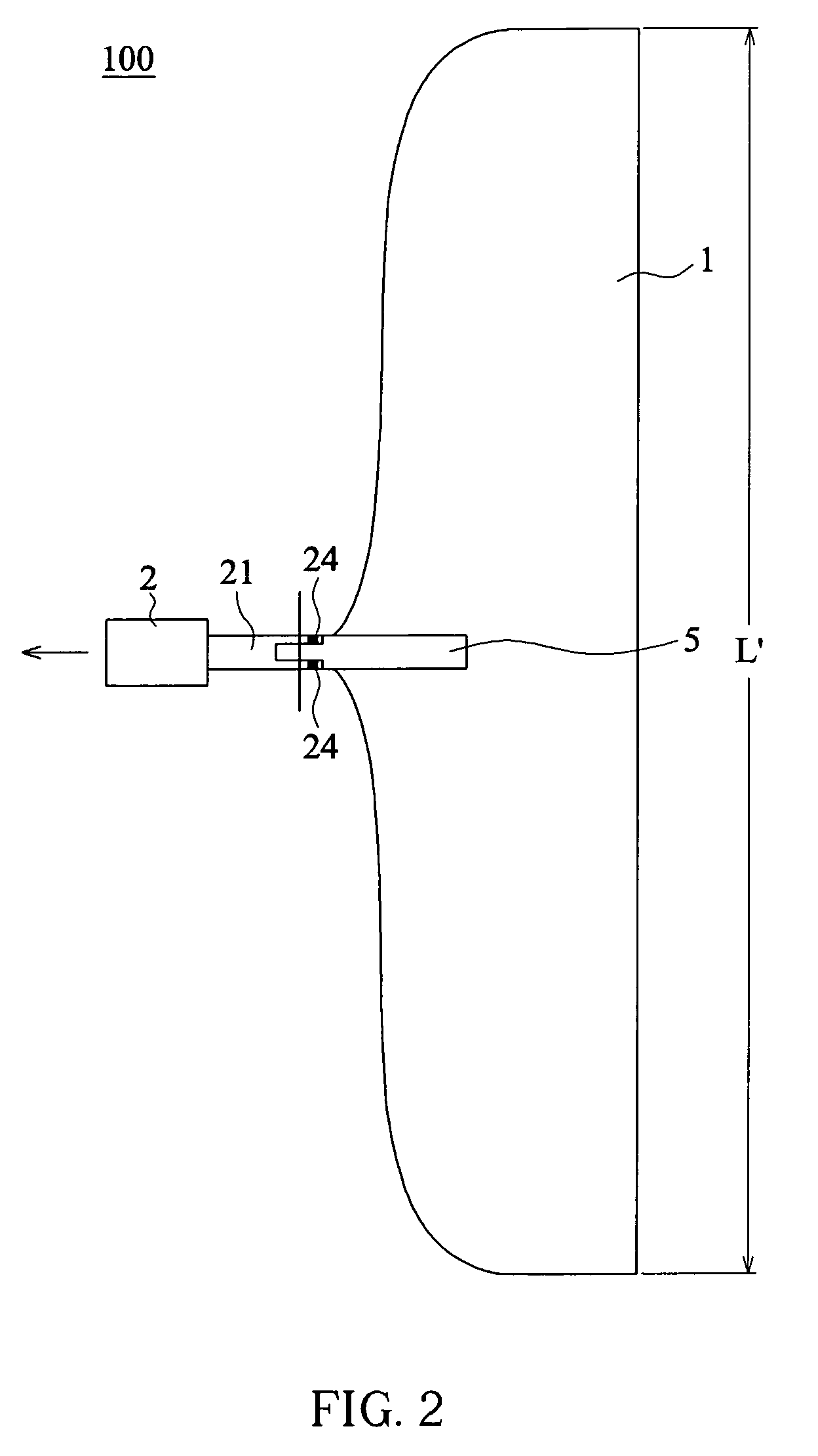
2. Foil Pitch Control with a Joint

[0031]To obtain an effective thrust, a foil undergoing heaving motion needs to have appropriate pitch angle variation associated with the motion. The invention provides an underwater joint that enables the foil pitch angle to be self-adjusted by using the variation of fluid dynamic lift acting on the foil and...


PUM


Abstract

An oscillating-foil type underwater propulsor with a joint provided in the invention, the propulsor including a streamline foil having a foil surface being parallel to a water surface and a span length of at least twice as long as an average chord length of the streamline foil, and a heaving mechanism undergoing heaving motion perpendicular to a propulsion direction of the propulsor and having a transmission section, wherein the transmission section is pivotally connected to the streamline foil to form a joint, the joint being provided at the middle of the span length and having a rotation center located within a circular area, which has a radius of one third of the average chord length and is centered at the point one third of the average chord length ahead of the lifting center of the streamline foil.

Description

BACKGROUND OF THE INVENTION[0001]1. Field of the Invention[0002]The invention relates generally to an underwater propulsor, in particular to an oscillating-foil type underwater propulsor with a joint. The underwater propulsor of the invention mimics the tail movement of fast moving cetaceans or tunas and provides an oscillating foil and a joint for achieving better propulsion efficiency.[0003]2. Description of Related Art[0004]Regarding conventional underwater propulsors, there are a variety of applications such as flippers for diving or snorkeling, paddles for canoeing or Chinese dragon boats, and propellers of container ships or ocean liners. As an auxiliary equipment to facilitate propulsion, the flippers have long been important in the history of human underwater activities. Such a flipper has an appearance resembling the webbed toes of a frog, but it actually functions like a tail fin of slow moving fish. For a flat structure such as the flipper, the flat structure can easily c...

Claims


Application Information

Patent Timeline
Patent Type & Authority Patents(United States)
IPC IPC(8): B63H1/36
CPCB63H1/32
Inventor WU, CHUN-KAI
Owner CHANG JUNG CHRISTIAN UNIV
Why Eureka
Try Eureka