
Reducing withdrawal force in a safety IV catheter

a technology of safety iv catheter and withdrawal force, which is applied in the direction of catheters, manufacturing tools, infusion syringes, etc., can solve the problems of needle grates, and achieve the effect of reducing the withdrawal force and friction caused

Active Publication Date: 2010-06-29
BECTON DICKINSON & CO
View PDF28 Cites 65 Cited by
  • Summary
  • Abstract
  • Description
  • Claims
  • Application Information

AI Technical Summary

Benefits of technology

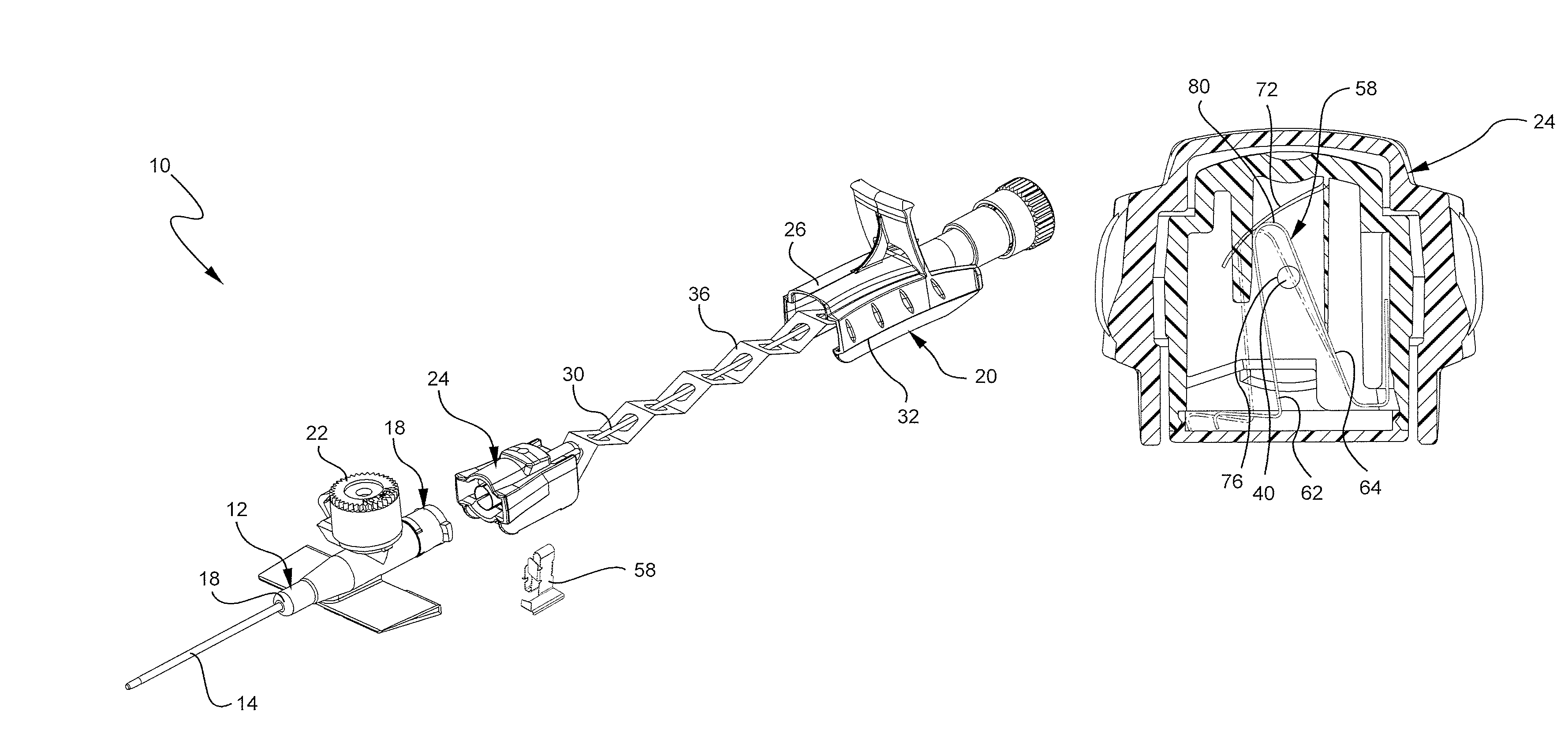
The present invention provides a needle tip shield that reduces the withdrawal force and friction caused as a needle is withdrawn through a needle tip shield device. This is developed to address problems and needs in the art that have not yet been fully resolved by currently available vascular access systems and methods. The needle tip shield assembly includes a needle cap with a V-clip and a low friction surface, which may be a lubricant, polymer, soft metal, or other suitable material. The low friction surface may be adhered to an adjoining structure or included on the needle itself. The method of manufacturing the extravascular system for accessing the vasculature of a patient includes preparing the needle tip shield assembly and inserting the needle into the catheter assembly. The needle tip shield assembly reduces the withdrawal force and friction of the needle as it is withdrawn, improving the overall performance of the extravascular system.

Problems solved by technology

As the introducer needle is withdrawn from the patient, the needle grates or otherwise causes friction as it slides past the metal components within the needle tip shield device.

Method used


Image

  • Reducing withdrawal force in a safety IV catheter
  • Reducing withdrawal force in a safety IV catheter
  • Reducing withdrawal force in a safety IV catheter

Examples


Embodiment Construction

[0026]The presently preferred embodiments of the present invention will be best understood by reference to the drawings, wherein like reference numbers indicate identical or functionally similar elements. It will be readily understood that the components of the present invention, as generally described and illustrated in the figures herein, could be arranged and designed in a wide variety of different configurations. Thus, the following more detailed description, as represented in the figures, is not intended to limit the scope of the invention as claimed, but is merely representative of presently preferred embodiments of the invention.

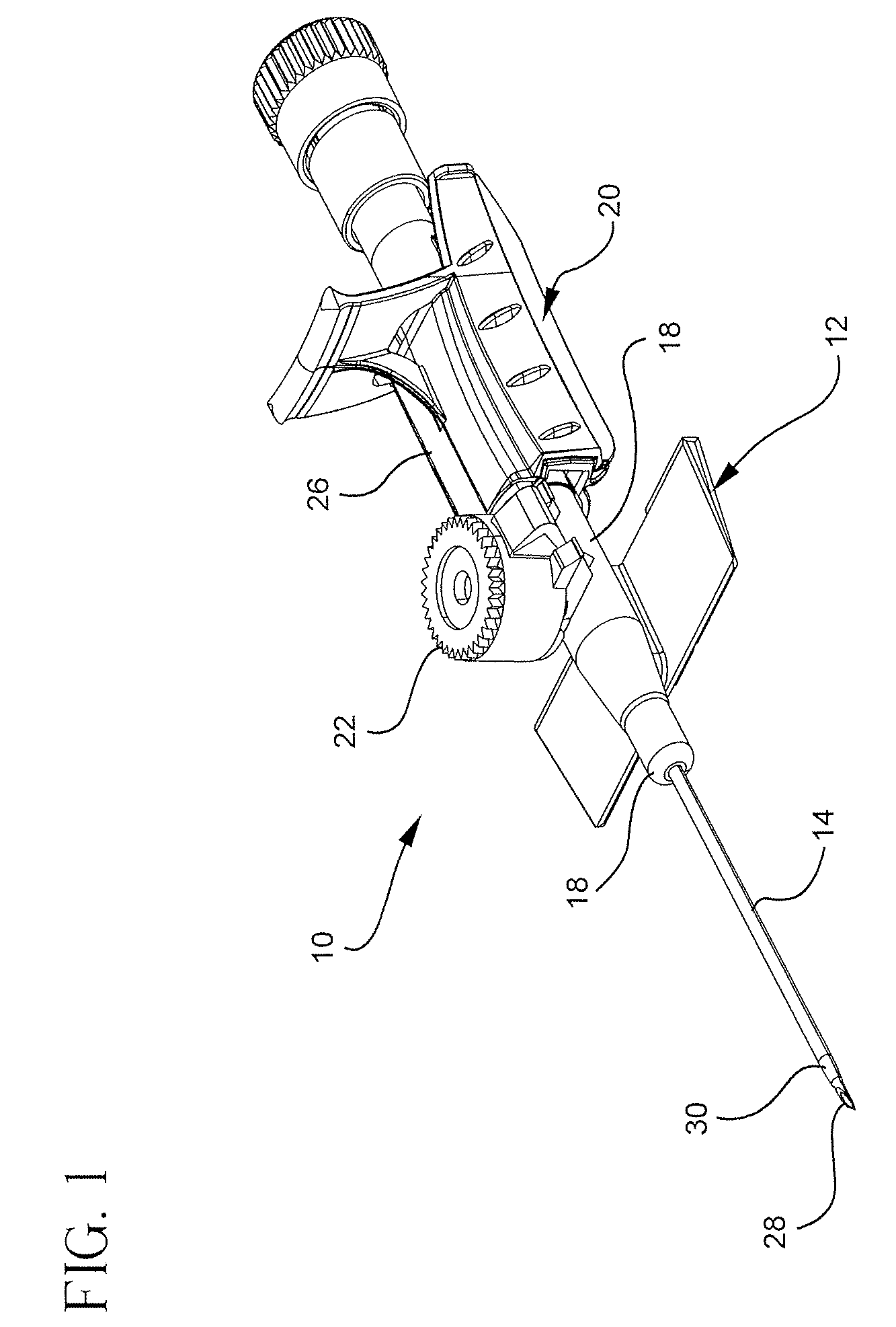
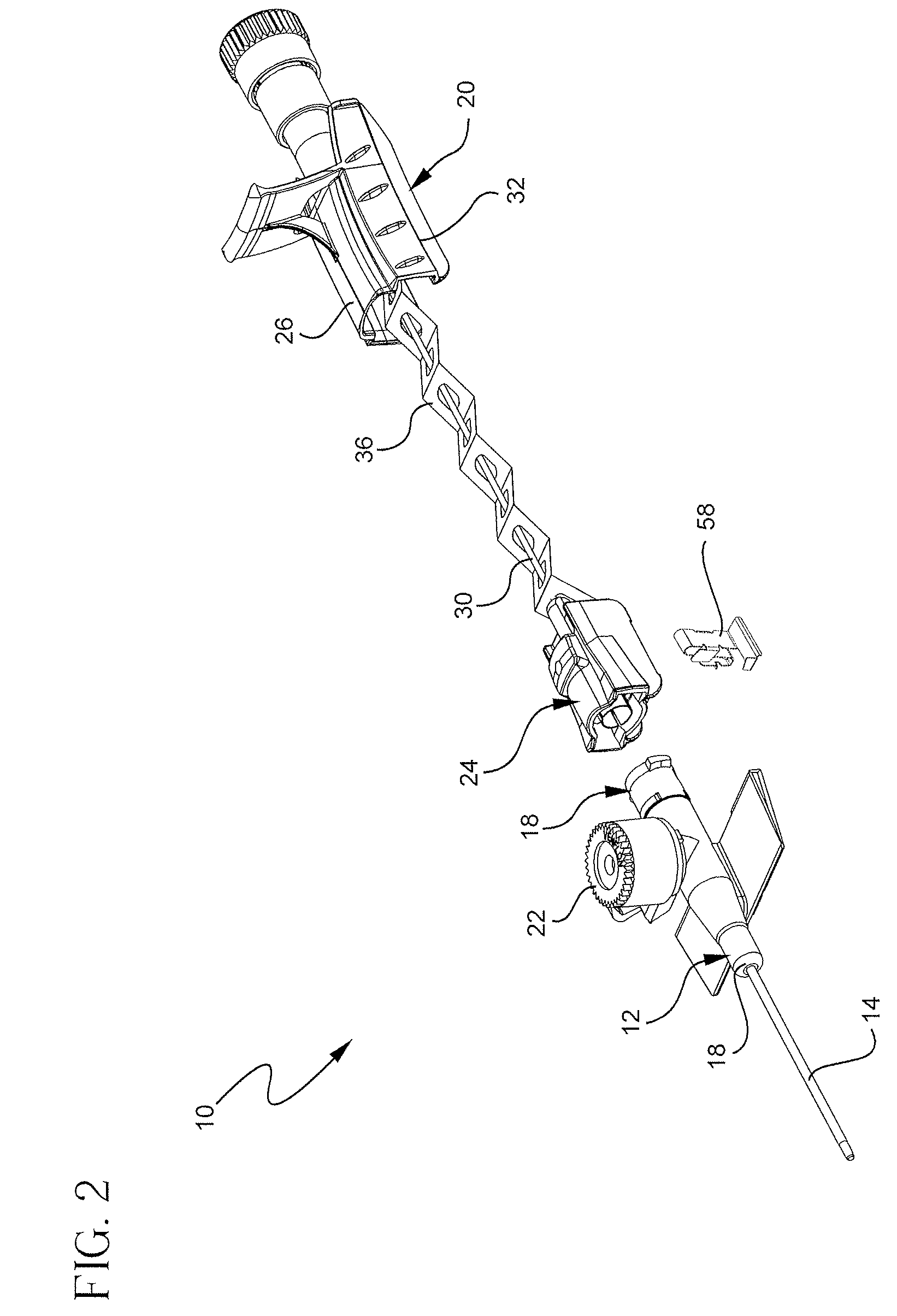
[0027]Referring to FIG. 1, a perspective view illustrates an example of an extravascular system 10 of multiple extravascular systems. In this example the extravascular system 10 includes a catheter assembly 12 and a needle assembly 20. The catheter assembly 12 includes a vascular access device, such as a catheter 14, partially housed within a catheter...


PUM

PropertyMeasurementUnit
frictionaaaaaaaaaa
friction surfaceaaaaaaaaaa
structureaaaaaaaaaa

Abstract

An extravascular system for accessing the vasculature of a patient may include a catheter adapter, a needle, and / or a needle tip shield assembly. The needle tip shield assembly may have a needle cap, and the needle cap may have a needle shield and at least one low friction surface. The needle may be disposed within the catheter assembly and the needle tip shield assembly. The low friction surface may reside between the needle shield and the needle. The at least one low friction surface may reside on the needle, on the V-clip, and / or on a structure located between the needle and the V-clip.

Description

RELATED APPLICATIONS[0001]This application claims the benefit of U.S. Provisional Application No. 60 / 867,041, filed Nov. 22, 2006, entitled REDUCING WITHDRAWAL FORCE IN A SAFETY IV CATHETER, which is incorporated herein by reference.BACKGROUND OF THE INVENTION[0002]This invention relates generally to extravascular systems and methods, including catheter assemblies and devices used with catheter assemblies. Generally, extravascular systems are used for communicating fluid with the vascular system of patients. For example, catheters are used for infusing fluid, such as normal saline solution, various medicaments, and total parenteral nutrition, into a patient, withdrawing blood from a patient, or monitoring various parameters of the patient's vascular system.[0003]A common type of intravenous (IV) catheter is an over-the-needle peripheral IV catheter. As its name implies, an over-the-needle catheter is mounted over an introducer needle having a sharp distal tip. At least the inner sur...

Claims


Application Information

Patent Timeline
Patent Type & Authority Patents(United States)
IPC IPC(8): A61M5/178
CPCA61M25/0625A61M25/0637A61M5/3275Y10T29/49826A61M2005/325A61M25/0618
Inventor GLOWACKI, KRISTOFFERTHORNE, JOHAN FREDRIKLARSSON, LARS-.ANG.KE LENNARTHAGER, JORGEN BRUNO
Owner BECTON DICKINSON & CO
Learn More