Photo-luminescent liquid crystal display including a blue dichroic mirror layer

a liquid crystal display and dichroic mirror technology, applied in optics, instruments, nanotechnology, etc., can solve the problems of significant optical loss, narrow viewing angle and orientation, etc., and achieve the effect of high-quality images

Inactive Publication Date: 2010-06-29
SAMSUNG ELECTRONICS CO LTD
View PDF9 Cites 56 Cited by
  • Summary
  • Abstract
  • Description
  • Claims
  • Application Information

AI Technical Summary

Benefits of technology

[0012]The present invention may provide a photo-luminescent liquid crystal display (PL LCD) capable of displaying a high quality image.
[0013]The present invention also may provide a PL LCD having a high light utilization efficiency.
[0020]The PL LCD may further include an ultraviolet (UV) filter blocking external UV light and preventing absorption of UV light into the light emitting layers.

Problems solved by technology

The red, green, and blue color filters each transmit only light of a specific wavelength, which is one third of that of white light, resulting in significant optical loss.
The drawback of the proposed PL LCD is that it has a narrow viewing angle and orientation because light emitted from a blue pixel has a polarization component.

Method used


Image

  • Photo-luminescent liquid crystal display including a blue dichroic mirror layer
  • Photo-luminescent liquid crystal display including a blue dichroic mirror layer
  • Photo-luminescent liquid crystal display including a blue dichroic mirror layer

Examples


Embodiment Construction

[0033]Hereinafter, the present invention will be described more fully with reference to the accompanying drawings, in which exemplary embodiments of the invention are shown.

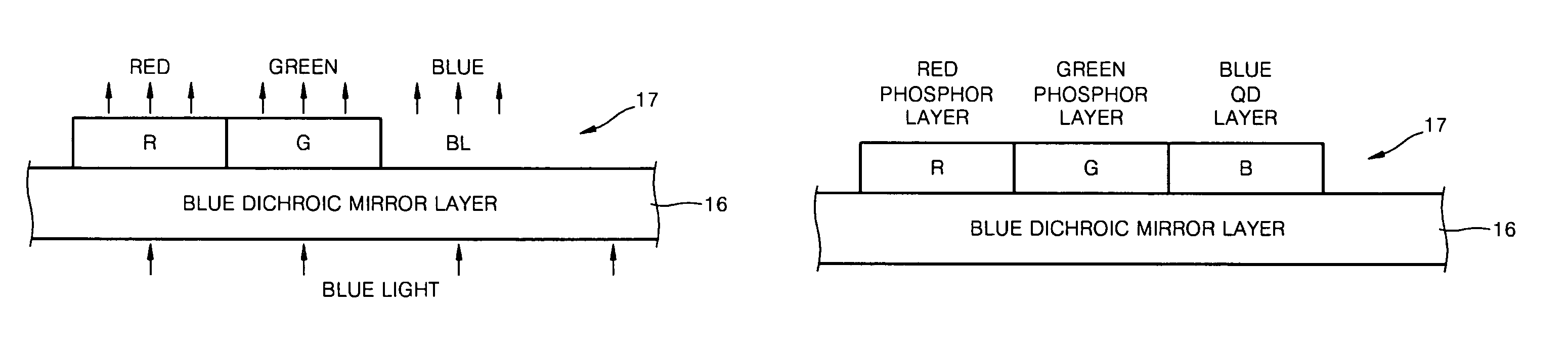
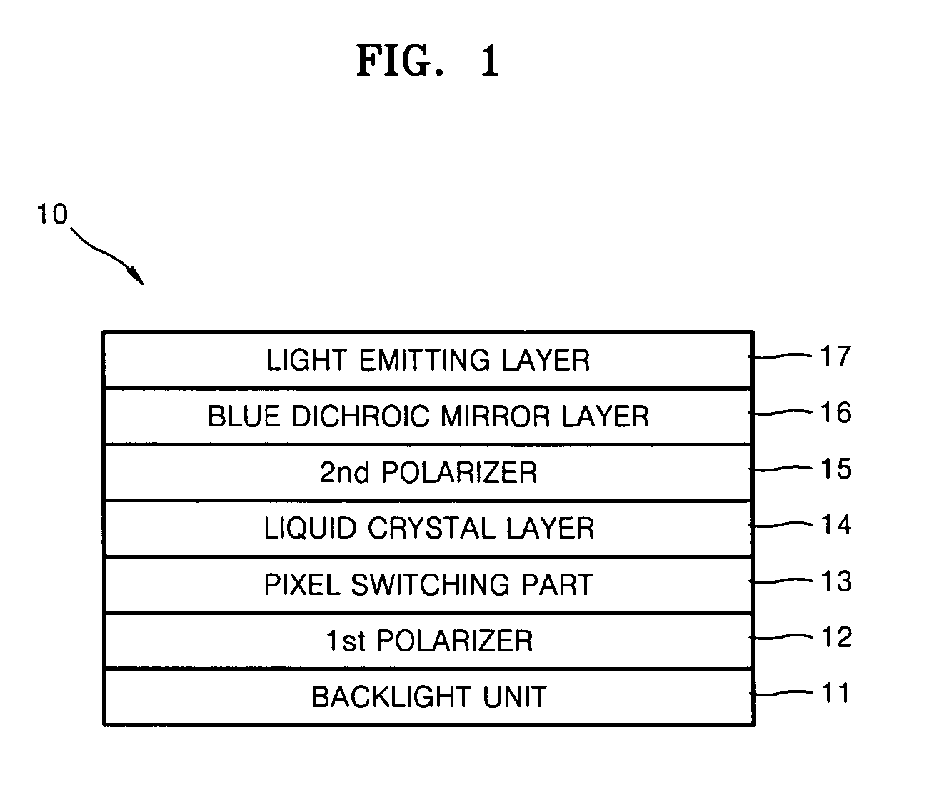
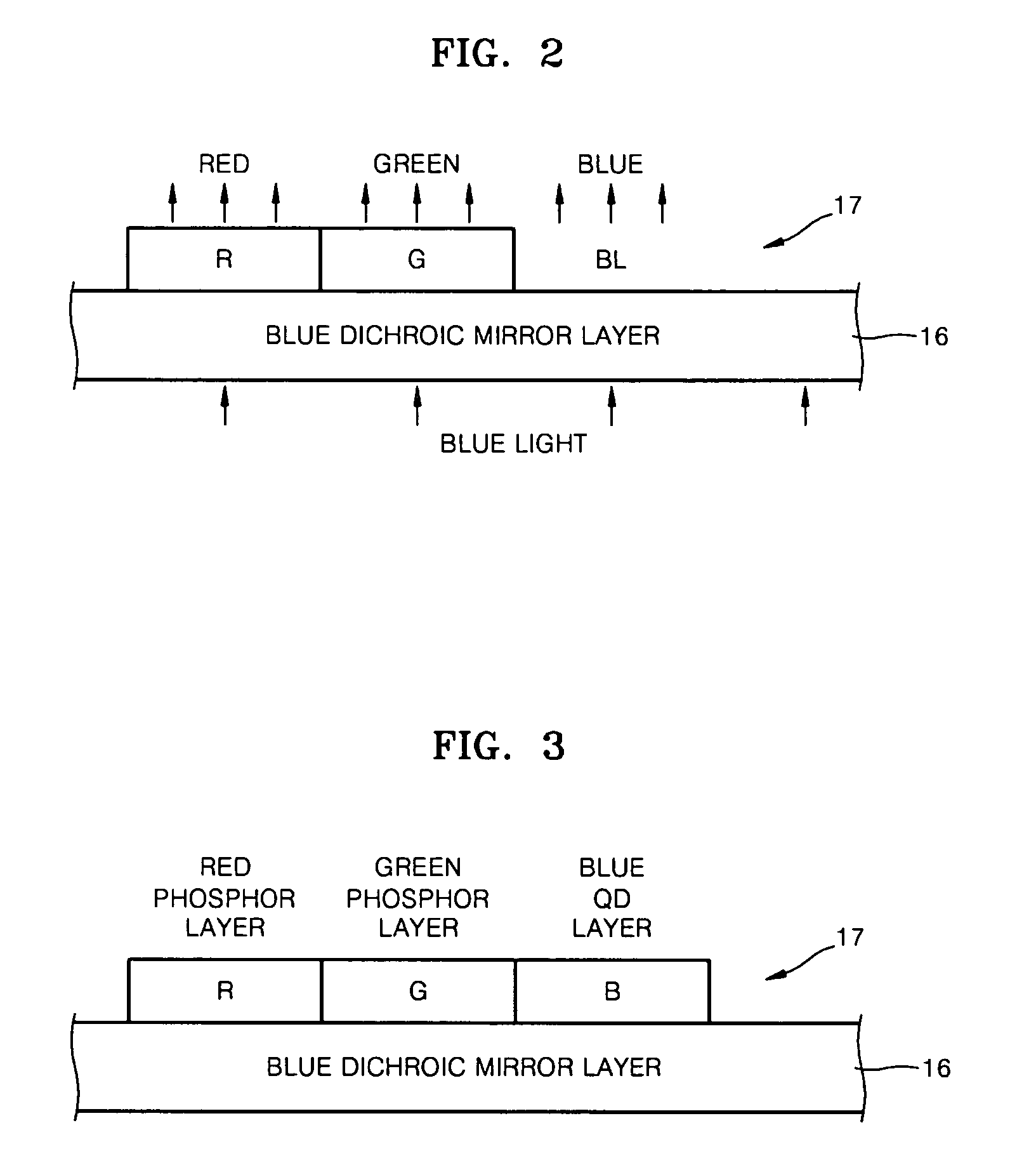
[0034]FIG. 1 is a cross-sectional view of a liquid crystal display (LCD) 10 according to an embodiment of the present invention. Referring to FIG. 1, the LCD 10 includes a backlight unit 11 generating blue light, a liquid crystal layer 14 modulating light generated from the backlight unit 11, a pixel switching part 13 driving the liquid crystal layer 14 with respect to each pixel, a light emitting layer 17 emitting light due to the blue light passing through the liquid crystal layer 14, a first polarizer 12 disposed between the pixel switching part 13 and the backlight unit 11, a second polarizer 15 disposed between the liquid crystal layer 14 and the light emitting layer 17, and a blue dichroic mirror layer 16. For convenience of explanation, a front plate and a rear plate are not illustrated in FIG. 1.

[0035]The...


PUM

PropertyMeasurementUnit
wavelengthaaaaaaaaaa
diameteraaaaaaaaaa

Abstract

A photo-luminescent (PL) liquid crystal display (LCD) including a blue dichroic mirror layer disposed under a light emitting layer is provided. Visible light generated from the light emitting layer is mostly reflected to the front side of the PL LCD, thereby increasing the light utilization efficiency thereof. A blue PL quantum dot layer is formed in blue light regions, thereby improving a narrow viewing angle and an orientation in blue pixels. An ultraviolet (UV) filter blocking UV light in the ambient light is formed to protect the light emitting layer from the excitation caused by external light, thereby preventing degradation of contrast caused by an undesired light emission.

Description

CROSS-REFERENCE TO RELATED PATENT APPLICATION[0001]This application claims the benefit of Korean Patent Application No. 10-2005-0047346, filed on Jun. 2, 2005, in the Korean Intellectual Property Office, the disclosure of which is incorporated herein in its entirety by reference.BACKGROUND OF THE DISCLOSURE[0002]1. Field of the Disclosure[0003]The present disclosure relates to a liquid crystal display (LCD), and more particularly, to a photo-luminescent (PL)-LCD with high light utilization efficiency.[0004]2. Description of the Related Art[0005]LCDs are non-emissive displays that require a separate backlight unit and red, green, and blue color filters for pixels to display a color image on a screen.[0006]The red, green, and blue color filters respectively separate white light emitted from the backlight unit into red, green, and blue lights. The red, green, and blue color filters each transmit only light of a specific wavelength, which is one third of that of white light, resulting i...

Claims


Application Information

Patent Timeline
Patent Type & Authority Patents(United States)
IPC IPC(8): G02F1/1335
CPCB82Y10/00G02F1/133617B82Y20/00G02F2202/108G02F2202/36G02F2202/106G02F2201/086G02F1/1335
Inventor IM, SEOUNG-JAEKIM, BYUNG-KICHOI, JAE-YOUNG
Owner SAMSUNG ELECTRONICS CO LTD
Why Eureka
Try Eureka