Integrated protection, monitoring, and control system

a control system and integrated technology, applied in the direction of mechanical power/torque control, program control, electric devices, etc., can solve the problems of over-current condition, increased equipment size, and complicated switching operations used

Inactive Publication Date: 2010-06-29
ABB (SCHWEIZ) AG
View PDF234 Cites 253 Cited by
  • Summary
  • Abstract
  • Description
  • Claims
  • Application Information

AI Technical Summary

Problems solved by technology

Similar switchgear may also be used within an electric utility transmission system and a plurality of distribution substations, although the switching operations used may be more complex.
The failure of the monitoring system to record the system shutdown may mislead an operator to believe that an over-current condition has not occurred within the power distribution system, and as such, a proper corrective action may not be initiated by the operator.
As such, the control logic may undesirably attempt to connect the faulted circuit to an alternate source, thereby restoring the over-current condition.
In addition to the potential increase in operational defects which may occur using such devices, the use of multiple devices and interconnecting wiring associated with the devices may cause an increase in equipment size, an increase in the complexity of wiring the devices, and / or an increase in a quantity of devices installed.

Method used


Image

  • Integrated protection, monitoring, and control system
  • Integrated protection, monitoring, and control system
  • Integrated protection, monitoring, and control system

Examples


Embodiment Construction

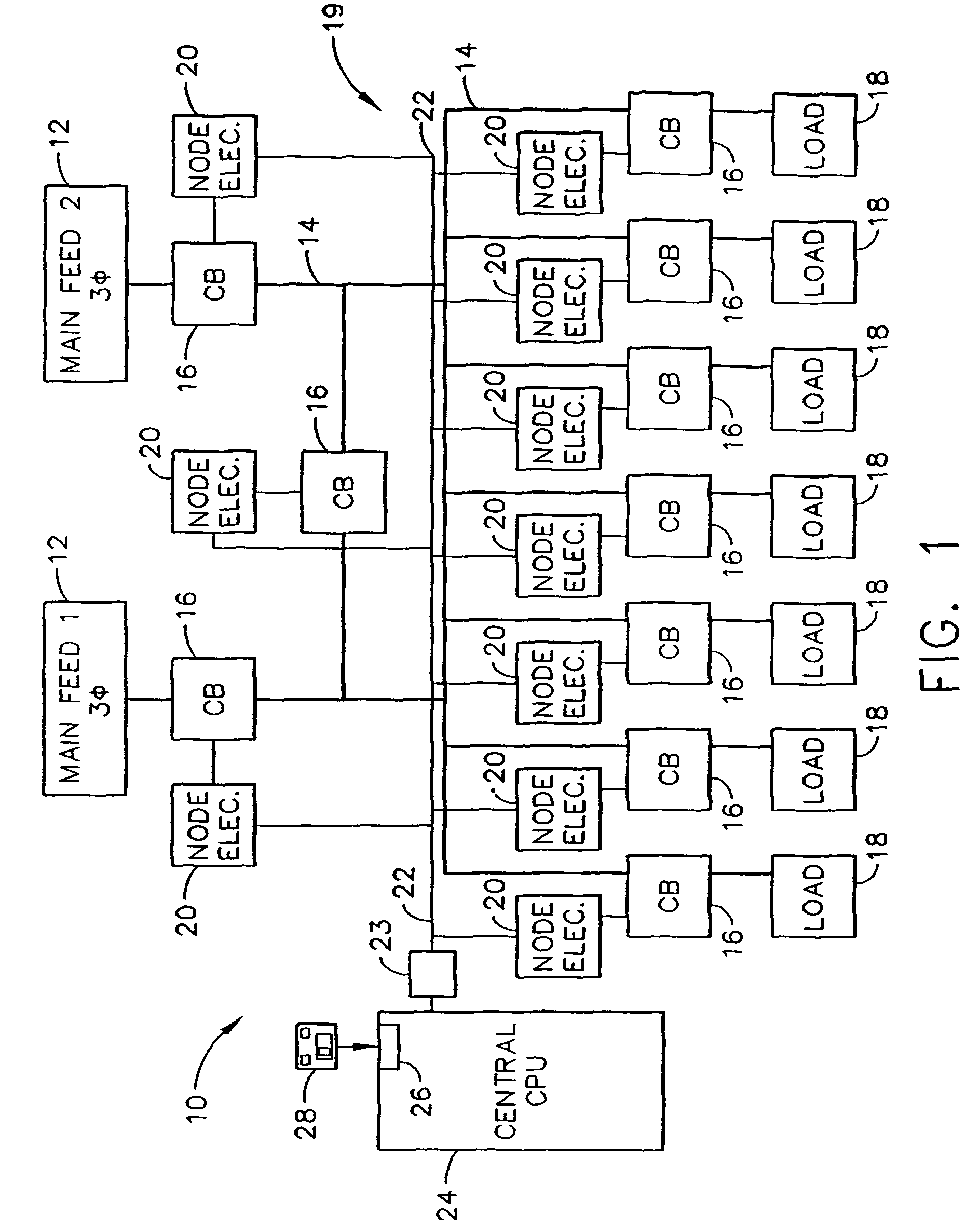
[0016]FIG. 1 illustrates an exemplary schematic illustration of a power distribution system 10, used by an industrial facility for example. In an exemplary embodiment, system 10 includes at least one main feed system 12, a power distribution bus 14, a plurality of power circuit switches or interrupters, also referred to herein as a circuit breakers (CB) 16, and at least one load 18, such as, but not limited to, motors, welding machinery, computers, heaters, lighting, and / or other electrical equipment.

[0017]In use, power is supplied to a main feed system 12, i.e. a switchboard for example, from a source (not shown) such as, but not limited to, a steam turbine, powered from, for example, a nuclear reactor or a coal fired boiler, a gas turbine generator, and a diesel generator. Power supplied to main feed system 12 is divided into a plurality of branch circuits using circuit breakers 16 which supply power to various loads 18 in the industrial facility. In addition, circuit breakers 16 ...


PUM


Abstract

A method and system for monitoring and controlling a power distribution system is provided. The system includes a plurality of circuit breakers and a plurality of node electronic units. Each node electronic unit is mounted remotely from an associated circuit breaker that is electrically coupled with one of the node electronic units. The system also includes a first digital network, and a first central control unit. The first central control unit and the plurality of node electronic units are communicatively coupled to the first digital network. The method includes receiving digital signals from each node electronic unit at the central control unit, determining an operational state of the power distribution system from the digital signal, and transmitting digital signals to the plurality of node electronic units such that the circuit breakers are operable from the first central control unit.

Description

CROSS REFERENCE TO RELATED APPLICATIONS[0001]This application is a continuation-in-part of U.S. application Ser. No. 10 / 373,572, filed Feb. 25, 2003, now U.S. Pat. No. 7,151,329, which issued on Dec. 19, 2006 and, which claims the benefit of U.S. Patent Provisional Application No. 60 / 359,544 filed on Feb. 25, 2002 for “Integrated Protection, Monitoring, and Control”, the contents of each of which are incorporated in its entirety herein by reference.BACKGROUND OF THE INVENTION[0002]This invention relates generally to electrical switchgear and more particularly, to a method and apparatus for protecting, monitoring, and controlling the electrical switchgear.[0003]In an industrial power distribution system, power generated by a power generation company may be supplied to an industrial or commercial facility wherein the power may be distributed throughout the industrial or commercial facility to various equipment such as, for example, motors, welding machinery, computers, heaters, lighti...

Claims


Application Information

Patent Timeline
Patent Type & Authority Patents(United States)
IPC IPC(8): G05D3/12G06F1/12H02H1/00H02H3/00H02H3/05H02H7/26H02J3/00H02J13/00H04L12/24
CPCG06F1/12H02H7/263H02J3/005H02J13/001H02J13/002H02J13/0024H02J13/0055H02J13/0062H02J13/0079H02J13/0086Y04S40/125H02H1/0061H02H3/006H02H3/05H02J13/0072H02J2003/001H02J2003/007H02J2003/146Y02B90/2615Y02B90/2623Y02B90/2638Y04S20/224Y04S40/121Y04S40/122Y04S40/124Y04S20/14Y02B70/3241Y02B90/224Y04S20/227Y02B90/2646H01H2300/03H02J2310/64H02J13/00018H02J13/00009H02J13/00012H02J13/00007H02J13/00001H02J2203/20H02J2310/12H02J13/00017H02J13/00016H02J13/00004H02J13/00028H02J13/00034H02J13/00036H02J13/0004Y02B70/30Y02B90/20Y04S20/222Y04S50/10Y04S20/221Y02B70/3225H02J3/007H02J3/00125Y02A30/60Y04S20/20
Inventor ANDARAWIS, EMAD ANDARAWISSEXTON, DANIEL WHITEEVANS, SCOTT CHARLESPEARLMAN, MARC ROBERTSCHNORE, JR., AUSTARS RAYMONDSEALING, CHARLES SCOTTPREMERLANI, WILLIAM JAMESBERKCAN, ERTUGRULWANG, WENDAITOPKA, TERRY MICHAELJIANG, MINGXIAO
Owner ABB (SCHWEIZ) AG
Why Eureka
Try Eureka