Power supply system and vehicle

a power supply system and power supply technology, applied in the direction of propulsion parts, propulsion using engine-driven generators, propulsion, etc., can solve the problems of increasing loss, unwanted electric energy shift between the batteries, and the inability of the same soc to charge the same battery, so as to prevent unwanted electric energy shift and avoid occurrence of loss

Active Publication Date: 2010-07-06
DENSO CORP
View PDF14 Cites 45 Cited by
  • Summary
  • Abstract
  • Description
  • Claims
  • Application Information

AI Technical Summary

Benefits of technology

[0007]The present invention has been made to solve such a problem, and one object of the present invention is to provide a power supply system and a vehicle suppressing unwanted electric energy shift between power storage units and avoiding occurrence of loss.
[0009]According to the power supply system in accordance with this aspect, the voltage reference value is limited so as not to fall below the maximum power storage voltage value of the power storage voltage values for the plurality of power storage units, and each of the plurality of power conversion units performs the voltage conversion operation in accordance with the voltage reference value. Since the voltage reference value is not less than a voltage value of the power line that can be charged by the power storage unit before control of the voltage conversion unit is started, each voltage conversion unit starts the voltage conversion operation immediately after the start of the control. Thereby, each voltage conversion unit operates to supply electric power from the corresponding power storage unit to the power line, and thus can avoid inflow of electric power from another power storage unit through the power line. Therefore, unwanted electric energy shift between the power storage units can be suppressed even when there is a voltage difference between the power storage units.
[0017]According to the vehicle in accordance with this aspect, the voltage reference value is limited so as not to fall below the maximum power storage voltage value of the power storage voltage values for the plurality of power storage units, and each of the plurality of power conversion units performs the voltage conversion operation in accordance with the voltage reference value. Since the voltage reference value is not less than a voltage value of the power line that can be charged by the power storage unit before control of the voltage conversion unit is started, each voltage conversion unit starts the voltage conversion operation immediately after the start of the control. Thereby, each voltage conversion unit operates to supply electric power from the corresponding power storage unit to the power line, and thus can avoid inflow of electric power from another power storage unit through the power line. Therefore, unwanted electric energy shift between the power storage units can be suppressed even when there is a voltage difference between the power storage units.
[0025]According to the present invention, a power supply system and a vehicle suppressing unwanted electric energy shift between power storage units and avoiding occurrence of loss can be implemented.

Problems solved by technology

However, batteries in the same SOC do not always have the same power storage voltage value (i.e., a voltage value at an open end), because the voltage value of each battery greatly varies depending on the temperature of the battery, the degree of deterioration, and the like, in addition to the SOC.
Therefore, when the batteries have different voltage values, a current corresponding to the voltage difference flows between the batteries, causing unwanted electric energy shift between the batteries and increasing loss.

Method used


Image

  • Power supply system and vehicle
  • Power supply system and vehicle
  • Power supply system and vehicle

Examples


first embodiment

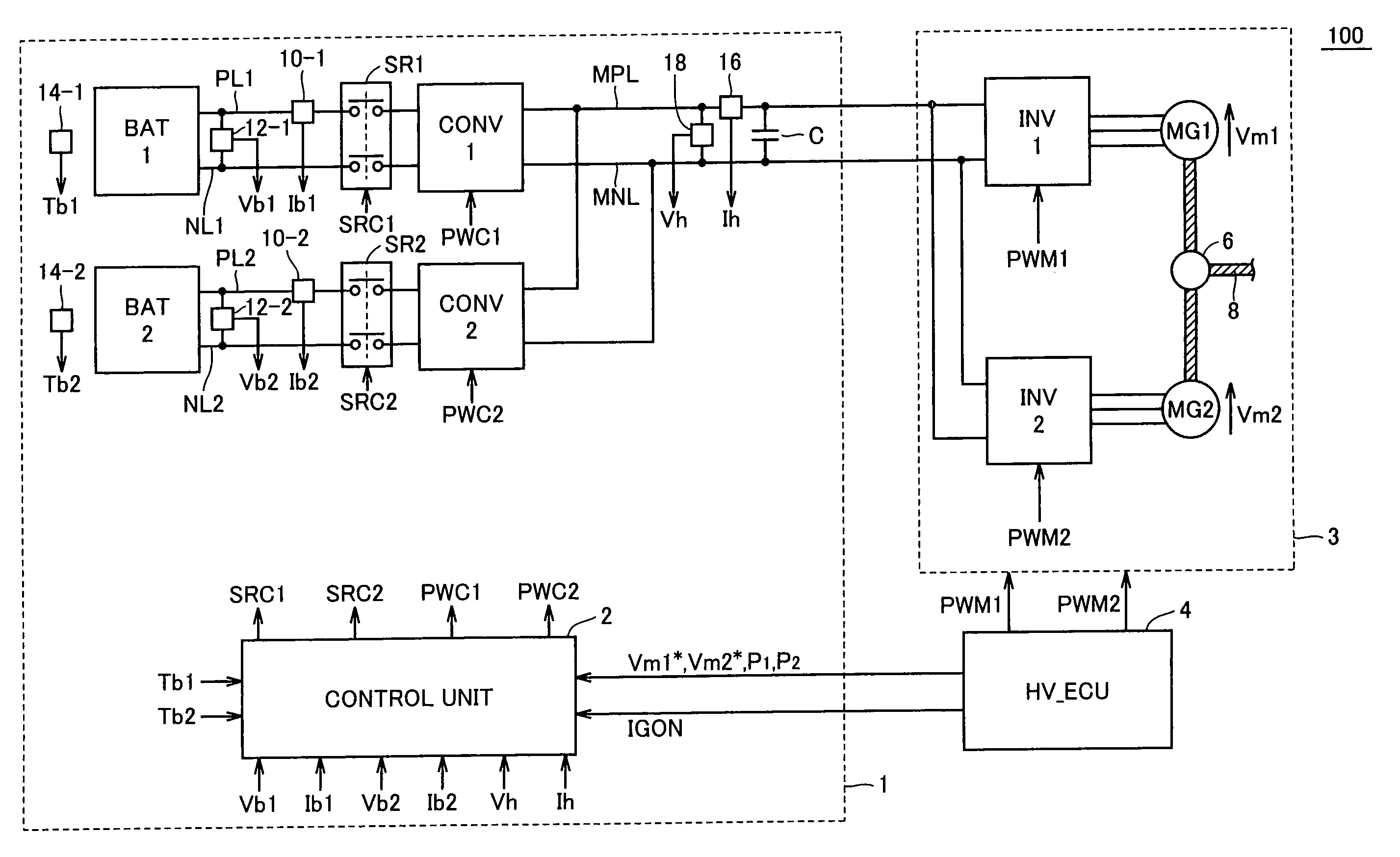
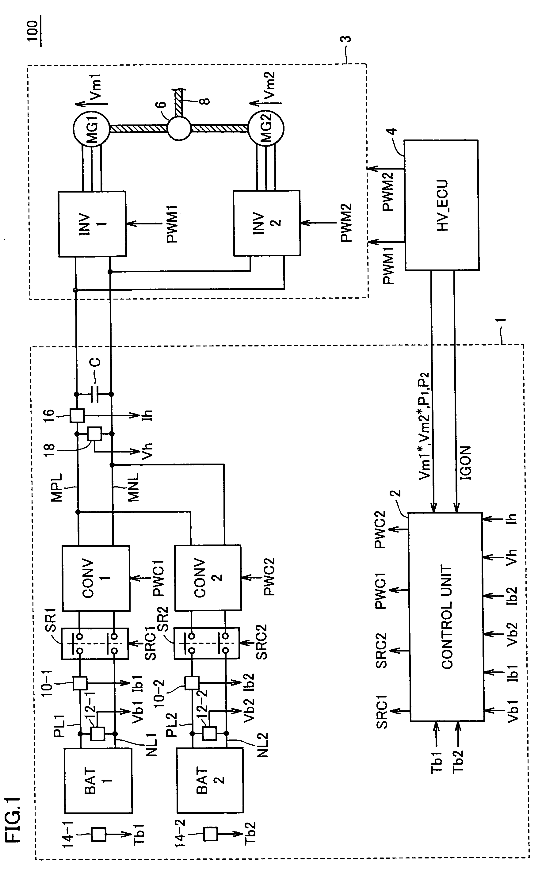
[0036]Referring to FIG. 1, a vehicle 100 including a power supply system 1 in accordance with a first embodiment of the present invention will be described. The first embodiment illustrates the case where a drive force generation unit 3 generating drive force for vehicle 100 is used as an example of a load device. Drive force generation unit 3 receives electric power from power supply system 1 to generate drive force, and supplies the drive force to wheels (not shown) of vehicle 100, causing vehicle 100 to run.

[0037]In the first embodiment, power supply system 1 having two power storage units as an example of a plurality of power storage units will be described. Power supply system 1 is configured to be capable of supplying and receiving DC power to and from drive force generation unit 3 through a main positive bus line MPL and a main negative bus line MNL.

[0038]Drive force generation unit 3 includes a first inverter INV1, a second inverter INV2, a first motor-generator MG1, and a s...

second embodiment

[0098]The present invention is applicable to a power supply system having three or more power storage units, in addition to the power supply system having two power storage units described above.

[0099]Referring to FIG. 7, a vehicle 100# including a power supply system 1# in accordance with a second embodiment of the present invention will be described. Since vehicle 100# includes power supply system 1# arranged instead of power supply system 1 in vehicle 100 shown in FIG. 1, the detailed description of drive force generation unit 3 and HV_ECU 4 will not be repeated. In the second embodiment of the present invention, power supply system 1# including N power storage units will be described.

[0100]Power supply system 1# includes converters CONV1, CONV2, . . . , CONVN, power storage units BAT1, BAT2, . . . , BATN, system relays SR1, SR2, . . . , SRN, battery current value detection units 10-1, 10-2, . . . , 110-N, battery voltage value detection units 12-1, 12-2, . . . , 12-N, and batter...


PUM


Abstract

A maximum value selection unit (50) receives battery voltage values (Vb1, Vb2) and outputs the maximum value thereof to a lower limit value limiting unit (54). A maximum value selection unit (52) receives required voltage values (Vm1*, Vm2*) and outputs the maximum value thereof to the lower limit value limiting unit (54). The lower limit value limiting unit (54) outputs a voltage reference value (Vh*) by limiting the value so as not to fall below an output value of the maximum value selection unit (50). Switching commands (PWC1, PWC2) are generated based on a control computation using a combination of a voltage feedback control element and a voltage feedforward element, and a control computation using a combination of a current feedback control element and a voltage feedforward element, respectively.

Description

TECHNICAL FIELD[0001]The present invention relates to a power supply system including a plurality of power storage units and a vehicle equipped with the power supply system. In particular, the present invention relates to a technique suppressing unwanted electric energy shift between power storage units.BACKGROUND ART[0002]In recent years, considering environmental issues, attention has been paid to a vehicle employing an electric motor as a source of drive force, such as an electric vehicle, a hybrid vehicle, and a fuel cell vehicle. Such a vehicle is equipped with a power storage unit implemented for example by a rechargeable battery for supplying electric power to the electric motor and converting kinetic energy to electric energy during regenerative braking.[0003]In such a vehicle employing an electric motor as a source of drive force, it is desirable to further increase the charge / discharge capacity of a power storage unit to improve acceleration performance and running perform...

Claims


Application Information

Patent Timeline
Patent Type & Authority Patents(United States)
IPC IPC(8): H02J1/00H02J3/00B60L50/16
CPCB60K6/48B60L11/1811B60L11/1868B60W10/08B60W10/26H02M3/1582H02M3/1584B60L7/14B60L11/005B60L11/123B60L11/14B60L11/1861B60L11/1864B60L15/2009B60K6/26B60K1/02B60L2240/549B60L2210/20B60W20/00B60W2510/242H02J7/0013H02P2201/09Y02T10/6221Y02T10/642Y02T10/7005Y02T10/7055Y02T10/7066Y02T10/725Y02T10/92Y02T90/127Y02T90/14B60L2210/10B60L2210/40B60L2240/421B60L2240/423B60L2240/545B60L2240/547Y02T10/7072B60L50/40B60L50/61B60L50/16B60L53/20B60L58/12B60L58/21B60L58/20Y02T10/62Y02T10/64Y02T10/70Y02T10/72H02J7/00B60L9/18B60W20/13Y02T90/12
Inventor ICHIKAWA, SHINJI
Owner DENSO CORP
Why Eureka
Try Eureka