Double-sided starter/generator for aircrafts

a starter/generator and double-sided technology, applied in the direction of electric generator control, magnetic circuit shape/form/construction, magnetic circuit rotating parts, etc., can solve the problems of reducing the operability of the engine, reducing the size of the generator, and reducing the ability to properly operate the engine, so as to reduce the radial force of the stator, reduce the thickness of the stator, and reduce the effect of mass and volum

Active Publication Date: 2010-07-06
GENERAL ELECTRIC CO
View PDF37 Cites 24 Cited by
  • Summary
  • Abstract
  • Description
  • Claims
  • Application Information

AI Technical Summary

Benefits of technology

[0015]An advantage of the present invention is that both the HP and LP spools can be connected to the single compact generator having less mass and volume compared to two separate electric machines.
[0016]Another advantage is that electrical power can be drawn form either or both sides of the motor / generator.
[0017]A further advantage of the present invention is that it incorporates all features from a double-sided structure motor / generator, including reduced radial force on the stator, reduced stator yoke thickness, reduced frame mass and lower cost of construction.
[0018]Yet another advantage of the present invention is that partial load can be sustained during some fault conditions, providing greater reliability.
[0019]Another advantage is that HP and LP generator sections may be individually optimized for speed range and power output in relation to number of poles.
[0020]Another advantage of the present invention is greatly reduced cost by providing the capability of using a larger power rating machine instead of two smaller machines, consuming smaller volume on the aircraft and making direct drive possible for some applications.

Problems solved by technology

When operating an aircraft engine at relatively low power levels, e.g., while idly descending from altitude, extracting this additional electrical power from the engine mechanical power may reduce the ability to operate the engine properly.
The LP engine spool provides an alternate source of power transfer, however, the relatively lower speed of the LP engine spool typically requires the use of a gearbox, as slow-speed electrical generators are often larger than similarly rated electrical generators operating at higher speeds.
However, extracting this additional mechanical power from an engine when it is operating at relatively low power levels (e.g., at or near idle descending from altitude, low power for taxi, etc.) may lead to reduced engine operability.
Tapping this low-speed mechanical power source without transformation result in impractically large generators.

Method used


Image

  • Double-sided starter/generator for aircrafts
  • Double-sided starter/generator for aircrafts
  • Double-sided starter/generator for aircrafts

Examples


Embodiment Construction

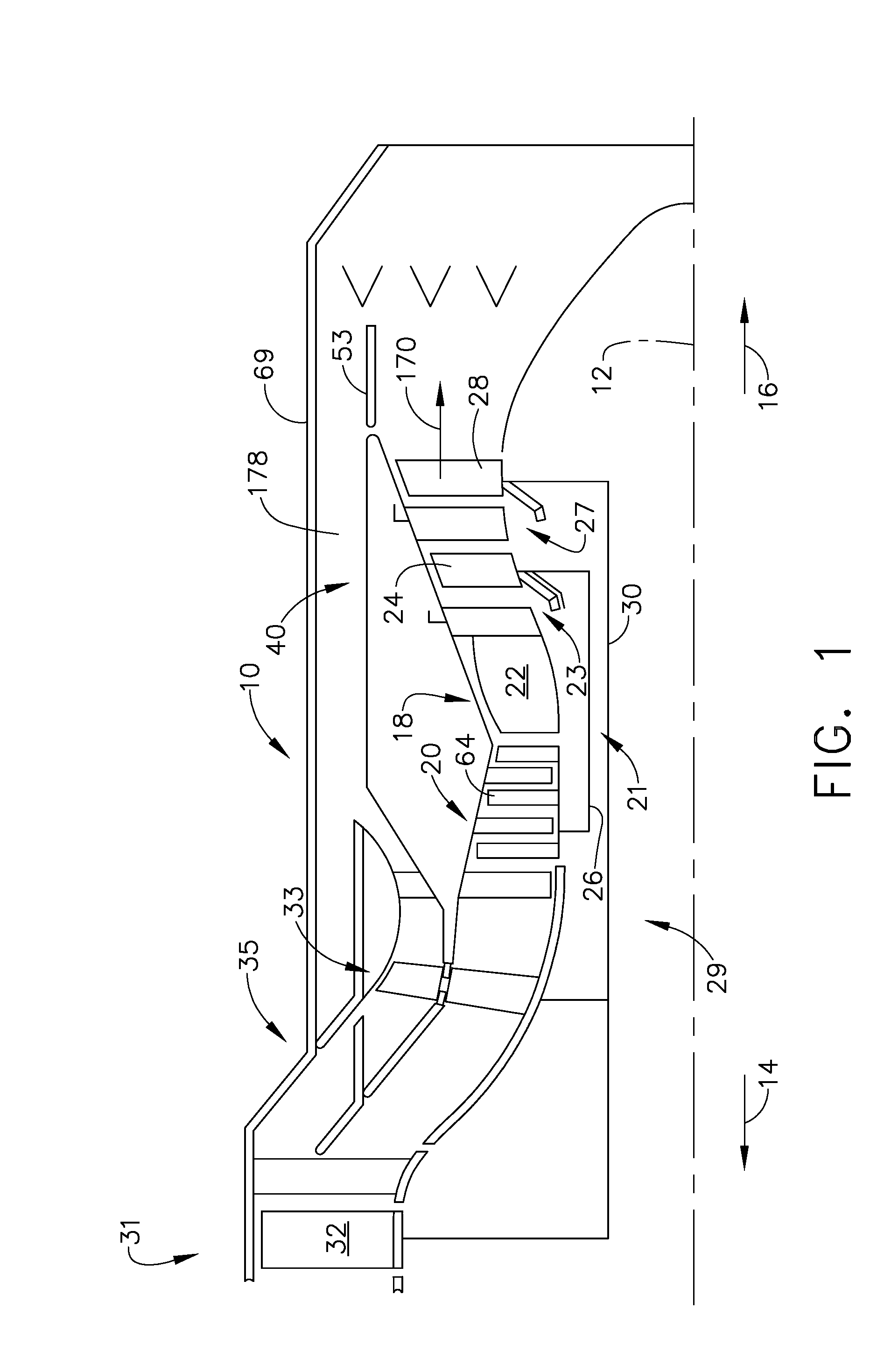
[0030]Illustrated in FIG. 1 is an exemplary turbofan engine 10 having a generally axially extending axis or centerline 12 generally extending in a forward direction 14 and an aft direction 16. The bypass turbofan engine 10 includes a core engine 18 (also called a gas generator) which includes a high pressure compressor 20, a combustor 22, and a high pressure turbine (HPT) 23 having a row of high pressure turbine blades 24, all arranged in a serial, axial flow relationship. High-pressure compressor blades 64 of the high-pressure compressor 20 are fixedly connected in driving engagement to the high pressure turbine blades 24 by a larger-diameter annular core engine shaft 26 which is disposed coaxially about the centerline 12 of the engine 10 forming a high pressure spool 21.

[0031]A combustor 22 in the core engine 18 mixes pressurized air from the high-pressure compressor 20 with fuel and ignites the resulting fuel and air mixture to produce combustion gases. Some work is extracted fro...


PUM


Abstract

An electromagnetic machine for extracting power from a turbine engine includes an outer rotor and an inner rotor rotatably supported adjacent to a stator. The stator is disposed between the inner and outer rotors. The stator has an inner set of windings disposed on an inner surface adjacent to the inner rotor, and an outer set of windings on an outer surface of the stator adjacent to the outer rotor. A plurality of permanent magnets are disposed on an inner surface of the outer rotor element and on an outer surface of the inner rotor element. Air gaps are defined between the outer surface of the stator and the outer permanent magnets, and between the inner surface of the stator portion and the inner permanent magnets. The inner stator windings form a set of multiple-phase windings, and the outer stator windings form a set of multiple-phase windings.

Description

FIELD OF THE INVENTION[0001]The present invention is directed to an electrical machine for aircrafts, and more particularly to an electrical motor / generator having coaxial dual rotors independently driven by a high- and low-pressure turbine shaft, respectively, of a gas turbine engine.BACKGROUND OF THE INVENTION[0002]A gas turbine engine generally includes one or more compressors followed in turn by a combustor and high and low pressure turbines. These engine components are arranged in serial flow communication and disposed about a longitudinal axis centerline of the engine within an annular outer casing. The compressors are driven by the respective turbines and compressor air during operation. The compressor air is mixed with fuel and ignited in the combustor for generating hot combustion gases. The combustion gases flow through the high and low pressure turbines, which extract the energy generated by the hot combustion gases for driving the compressors, and for producing auxiliary...

Claims


Application Information

Patent Timeline
Patent Type & Authority Patents(United States)
IPC IPC(8): H02K1/04
CPCH02K7/1823H02K21/12H02K16/00
Inventor QU, RONGHAIKERN, JOHN M.WU, WEIDE BEDOUT, JUAN M.SHAH, MANOJ R.EL-REFAIE, AYMAN MOHAMED FAWZI
Owner GENERAL ELECTRIC CO
Why Eureka
Try Eureka