PWM loop filter with minimum aliasing error

a loop filter and aliasing error technology, applied in the field of signal amplification, can solve the problems of significant voltage, high aliasing error, and high aliasing error of class amplifiers, and achieve the effect of minimal aliasing error

Active Publication Date: 2010-07-06
TEXAS INSTR INC
View PDF7 Cites 26 Cited by
  • Summary
  • Abstract
  • Description
  • Claims
  • Application Information

AI Technical Summary

Benefits of technology

[0007]The present invention is related to signal amplification, and in particular to a loop filter for a PWM based amplifier with minimum aliasing error.

Problems solved by technology

The phase response of a class A amplifier is quite linear and produces a high quality output, but the class A amplifier is extremely inefficient.
A class B amplifier is much more efficient than a class A amplifier, but is susceptible to crossover distortion when switching from one output transistor to the other.
Because it takes a small but significant amount of voltage for the output transistors to start conducting, portions of the input waveform that have a lower voltage than this turn-on voltage will not be reproduced faithfully by the class B amplifier.
While frequently used, all of these amplifier classes that operate in their linear ranges for all or some of the input cycle are relatively inefficient.
Many class D amplifier designs, however, suffer from distortion that limits their use in applications that require a high quality output such as high end audio amplifiers.
Distortion therefore remains a problem for class D amplifiers limiting their application in applications requiring a high quality output.

Method used


Image

  • PWM loop filter with minimum aliasing error
  • PWM loop filter with minimum aliasing error
  • PWM loop filter with minimum aliasing error

Examples


Embodiment Construction

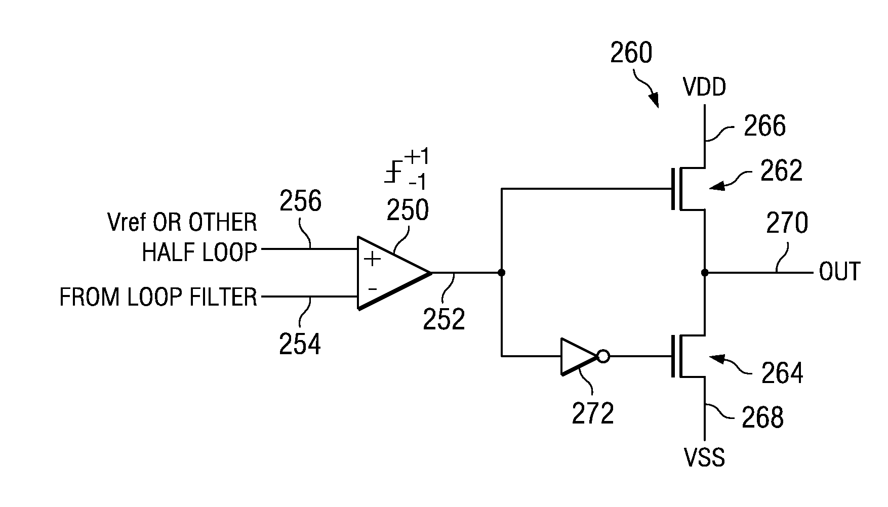
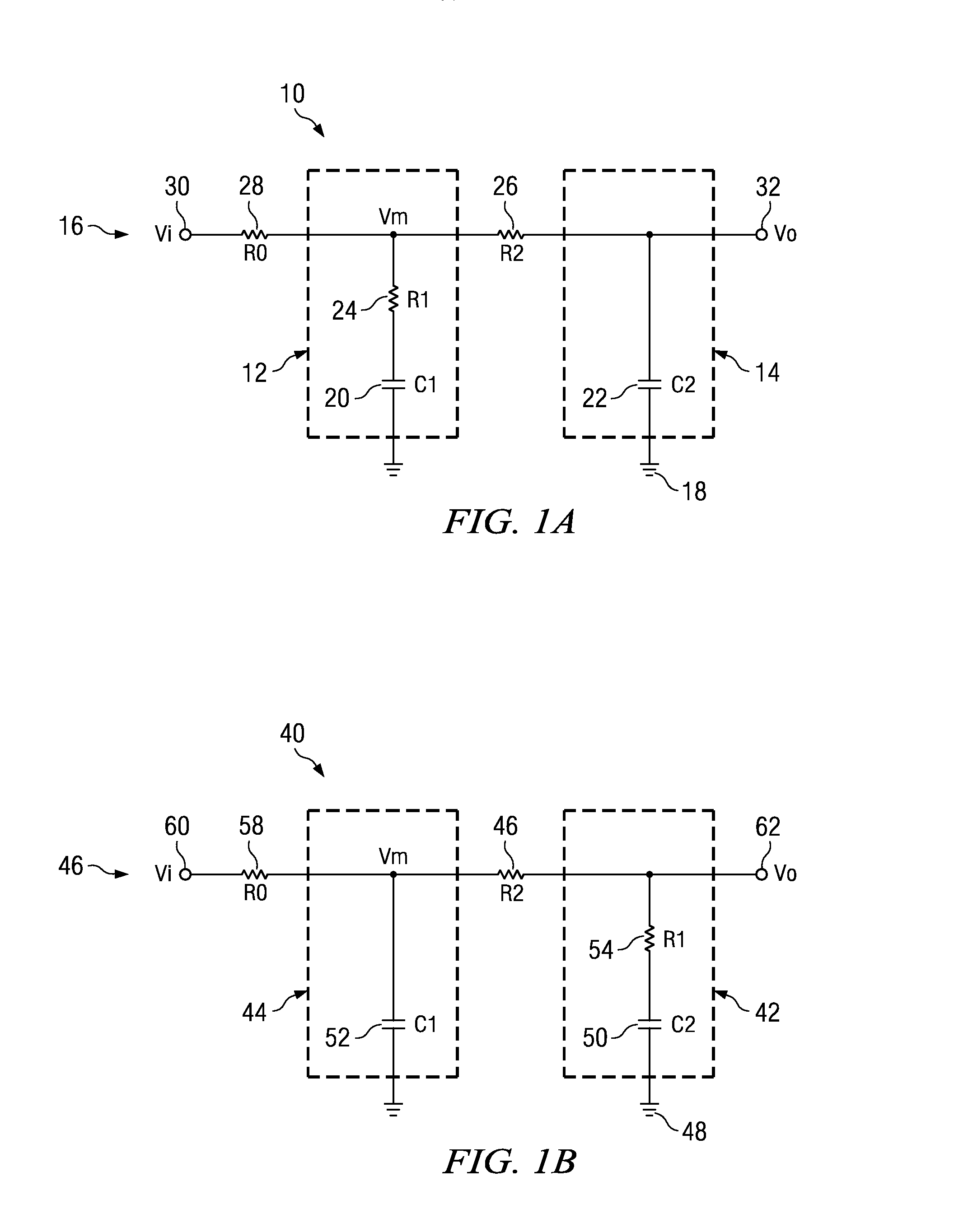
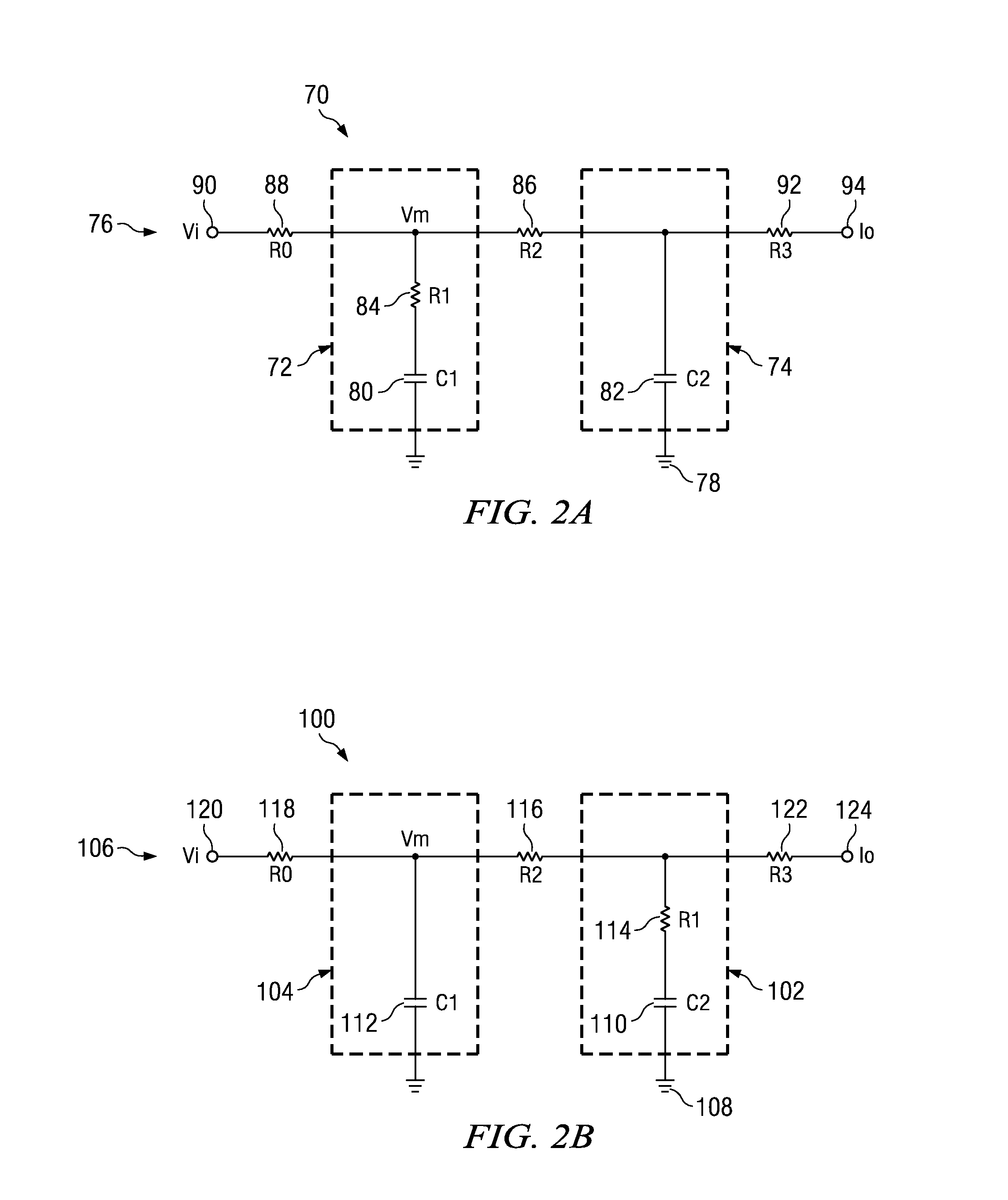
[0025]The present invention is related to signal amplification, and in particular to a loop filter for a PWM based amplifier with minimum aliasing error. The loop filter described herein may be used in a wide range of applications, such as in a PWM based class D audio power amplifier, or in an amplifier for motor control or power conversion systems, etc. Various embodiments of a PWM based amplifier with minimum aliasing error will be described herein. Generally, however, a PWM based amplifier contains a comparator that drives a switching power stage to produce an amplified PWM signal having a constant frequency and amplitude, in which the input signal is encoded in the duty cycle of the PWM signal. The comparator input is the audio input signal superimposed with a periodic carrier waveform with a frequency far above the frequency range of interest in the input signal. For example, in an audio amplifier, the frequency of the carrier waveform is far above the audible range (e.g. 200-8...


PUM


Abstract

One embodiment of an apparatus for filtering an electrical signal includes a loop filter with an input and an output that applies a transfer function to a signal at the input. The transfer function has substantially no real part. The loop filter has a dominant pole placed substantially at or above an upper frequency in the frequency range of interest for the loop filter.

Description

CROSS REFERENCE TO RELATED APPLICATION[0001]The present application claims priority to (i.e., is a non-provisional of) GB Pat. App. No. 0710186.8 entitled “PWM Loop with Minimum Aliasing Error Property”, and filed May 29, 2007 by Poulsen et al. The aforementioned application is assigned to an entity common hereto, and the entirety of the aforementioned application is incorporated herein by reference for all purposes.BACKGROUND OF THE INVENTION[0002]The present invention is related to signal amplification, and in particular to a loop filter for a PWM based amplifier with minimum aliasing error.[0003]Various types of electronic amplifiers exist for amplifying an electrical signal using one or more output devices such as transistors. Electronic amplifiers are commonly grouped into several classifications based on how they fundamentally operate and how they conduct electricity over the different portions of the input cycle. Class A amplifiers have one or more output transistors that con...

Claims


Application Information

Patent Timeline
Patent Type & Authority Patents(United States)
IPC IPC(8): H03F3/38
CPCH03F3/217H03H7/06H03H7/07
Inventor POULSEN, SOERENRISBO, LARS
Owner TEXAS INSTR INC
Why Eureka
Try Eureka