Waveguide bend having a square shape cross-section

a waveguide and cross-section technology, applied in waveguide devices, basic electric elements, electrical apparatus, etc., can solve the problems of round waveguides, insufficient electrical values for practical use, drawbacks of requiring relatively large bend radii, etc., and achieve good electrical transmission properties

Inactive Publication Date: 2010-07-06
KATHEIN WERKE KG
View PDF9 Cites 230 Cited by
  • Summary
  • Abstract
  • Description
  • Claims
  • Application Information

AI Technical Summary

Benefits of technology

[0012]Exemplary illustrative non-limiting implementations provide a 90° waveguide bend which has good electrical transmission properties, including cross-polarization decoupling, for both polarizations.

Problems solved by technology

In the case of a 90° bend of this type having a square cross section, reflections and transit absorptions can occur which in turn can yield insufficient electrical values for practical use.
A round waveguide has in this case a drawback of requiring relatively large bend radii, i.e. a space-saving 90° bend cannot be carried out.
Nevertheless, the technology herein has revealed that an embodiment of this type does not lead to the desired properties such as may be achieved within exemplary illustrative non-limiting implementations herein.

Method used


Image

  • Waveguide bend having a square shape cross-section
  • Waveguide bend having a square shape cross-section
  • Waveguide bend having a square shape cross-section

Examples


Embodiment Construction

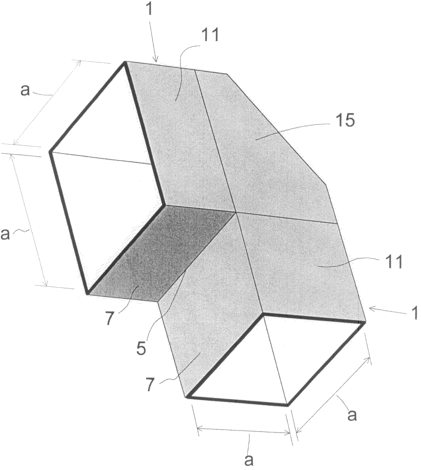
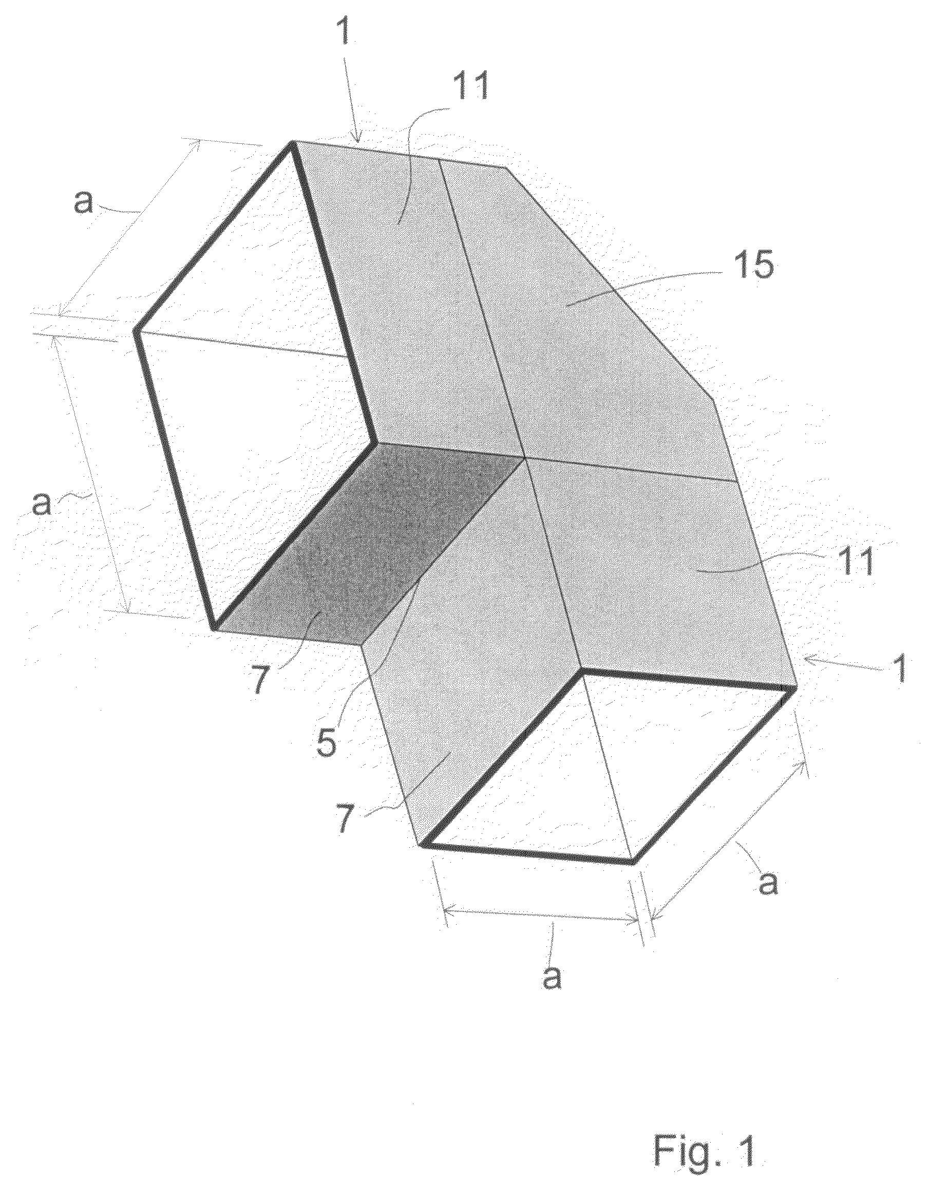
[0022]FIG. 1 is a schematic 3D illustration of an exemplary illustrative non-limiting embodiment of a 90° waveguide bend comprising two straight waveguide connectors 1 located perpendicularly to each other.

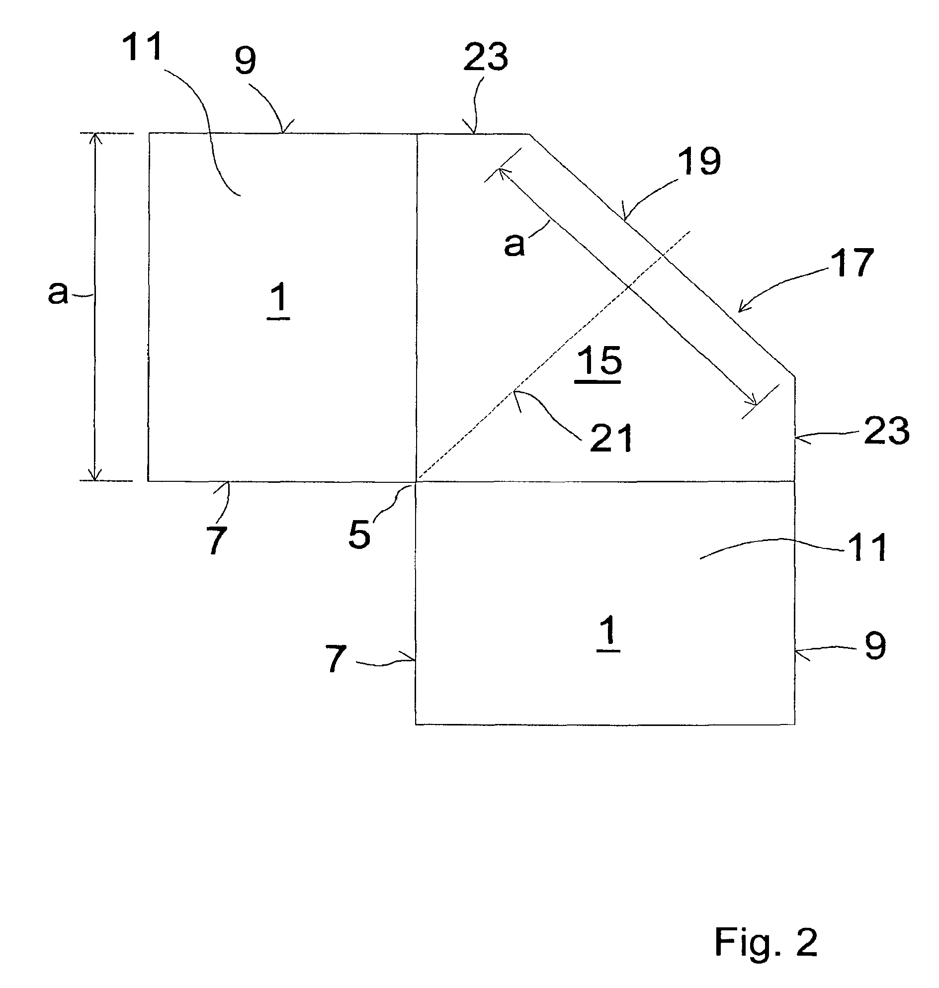
[0023]These waveguide connectors 1 have a square cross section having an edge length “a”.

[0024]The housing wall is made of electrically conductive material such as metal. This material is preferably a cast material, as the exemplary waveguide may be manufactured by casting. The cast or die-cast materials used are preferably zinc, brass and / or aluminum. Other materials or combinations and alloys of materials are also conceivable. The exemplary waveguide angle does not necessarily have to be manufactured by casting. Other manufacturing processes and methods are also possible.

[0025]The waveguide material may also be of a non-conductive, dielectric material if it is coated with an electrically conductive layer. While not shown, waveguide connectors 1 also can have, on their connection...


PUM


Abstract

An improved 90° waveguide bend has the following features:the waveguide bend has two waveguide connectors located perpendicularly to each other,the waveguide connectors have a square internal cross section having an edge length (a),between the two waveguide connectors there is provided an angular portion producing the 90° change in direction,the angular portion has externally to the 90° change in direction a chamfer as a delimiting wall for the waveguide bend, the waveguide channel being outwardly delimited by the chamfer, andthe chamfer has in the plane of curvature a length corresponding to the edge length (a) of the waveguide connectors which are square in cross section, ±less than 0.5%.

Description

FIELD[0001]The technology herein relates to a waveguide bend.BACKGROUND AND SUMMARY[0002]Waveguides, which are known to be used in microwave technology, have various lengths, cross-sectional shapes and sizes. Hollow waveguides often have rectangular cross sections. However, round cross-sectional shapes are also known. Conventionally, waveguides of this type are equipped at the start and at the end with a flange so to join rigidly together successive waveguide portions. In a waveguide path, the cross section is usually maintained. However, transitions from one cross-sectional shape to another cross-sectional shape are also known.[0003]It is often necessary to provide a change in a direction in a waveguide path. What are known as waveguide bends or waveguide angles are used for this purpose. Usually, these are 90° bends which change the direction of the lines of electric flux (E bends, E angles), i.e. in the case of rectangular waveguides via the broad side, or the direction of the li...

Claims


Application Information

Patent Timeline
Patent Type & Authority Patents(United States)
IPC IPC(8): H01P1/02
CPCH01P1/022
Inventor PRA.BETA.MAYER, PETERBLAIER, WERNERKACZMARSKI, KRZYSZTOF
Owner KATHEIN WERKE KG
Why Eureka
Try Eureka