Substrate-alignment using detector of substrate material

Active Publication Date: 2010-07-06
ULTRATECH INT INC
View PDF11 Cites 21 Cited by
  • Summary
  • Abstract
  • Description
  • Claims
  • Application Information

AI Technical Summary

Benefits of technology

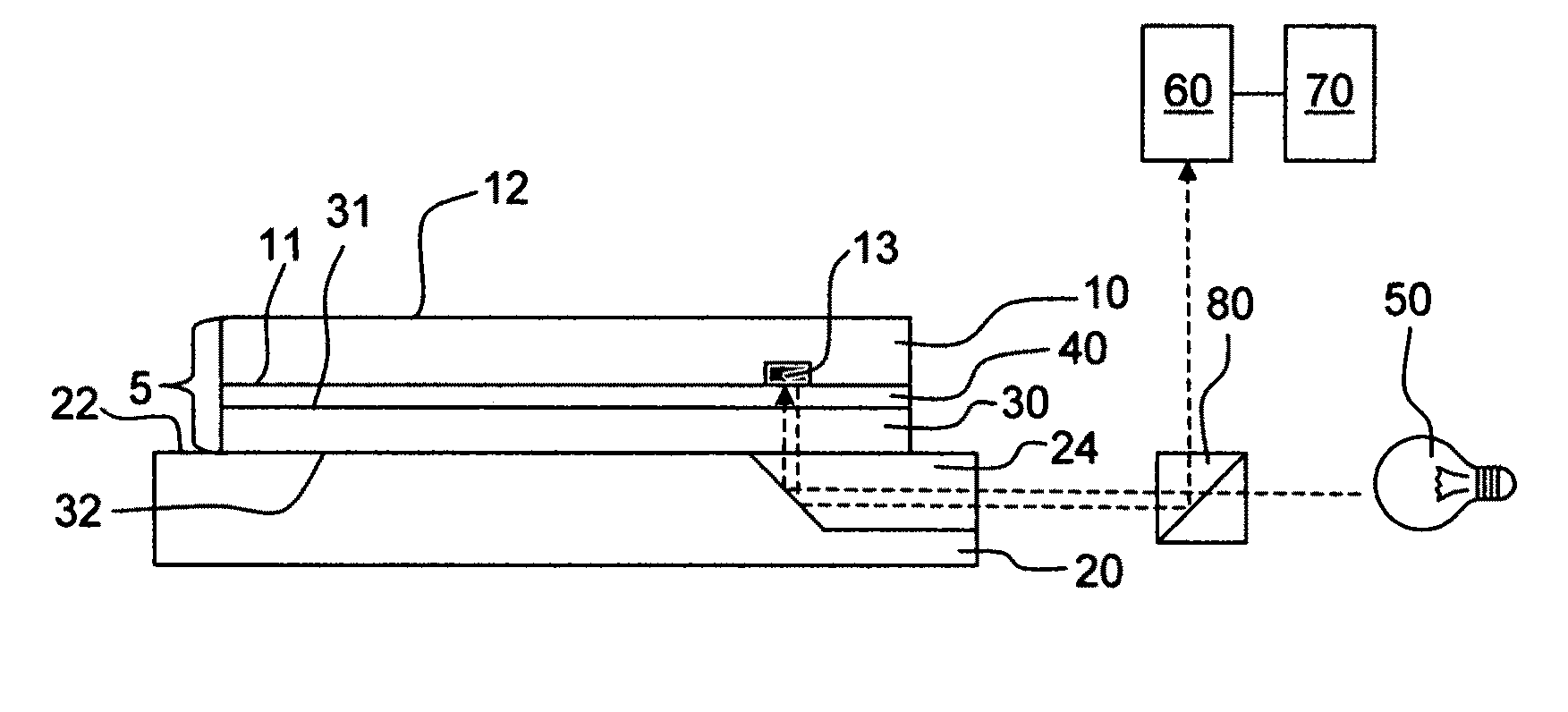
[0019]In a further aspect, an apparatus is provided for aligning a substrate. The apparatus includes a substrate as described above held by a substrate holder. Also included is a light source for generating light of the selected wavelength. The light source is positioned to direct light of the selected wavelength to the alignment feature, which may require it to pass through the first surface and the first layer. Further provided is an image detector as described above positioned to intercept light reflected from the alignment feature. Upon receiving the reflected light, the detector generates a signal that allows a machine vision system in signal-receiving relation to the image detector to recognize the reflective feature. The system may also determine from the signal the position of the reflective feature with a degree of precision sufficient for substrate alignment.
[0020]The apparatus may have the capability to determine the position of the reflective alignment feature to a precision described above as well as carrying out other variations or aspects of the above-described methods. For example, the light source may generate light of a selected wavelength that produces an image having sufficient contrast relative to the region adjacent the reflective alignment feature that the alignment feature may be correctly distinguished from other features and located with sufficient accuracy for alignment.

Problems solved by technology

Unfortunately, the technique requires the use of a specialized IR transparent stage and an otherwise unnecessary IR-reflective coating.
As a result, the technique is a relatively complex and expensive approach for alignment marks viewing.
However, the method is fairly complex in that the alignment light must pass through the reticle as well as through the wafer.

Method used


Image

  • Substrate-alignment using detector of substrate material
  • Substrate-alignment using detector of substrate material
  • Substrate-alignment using detector of substrate material

Examples


Embodiment Construction

Definitions and Overview

[0029]Before describing the present invention in detail, it is to be understood that this invention, unless otherwise noted, is not limited to specific substrates or materials, all of which may vary. It is also to be understood that the terminology used herein is for the purpose of describing particular embodiments only and is not intended to be limiting.

[0030]As used in this specification and the appended claims, the singular forms “a,”“an,” and “the” include both singular and plural referents unless the context clearly dictates otherwise. Thus, for example, reference to “a feature” includes a plurality of features as well as a single feature, reference to “a layer” includes a laminate of layers as well as a single layer, and the like.

[0031]Furthermore, terminology indicative or suggestive of a particular spatial relationship between elements of the invention is to be construed in a flexible rather than a rigid manner unless the context of usage clearly dict...


PUM


Abstract

Methods and apparatuses are provided for positioning a substrate having a target that may be located on either the front-side or the backside of the substrate. The optical detector that views the target contains a signal-generating material that is substantially identical to the substrate material.

Description

BACKGROUND[0001]1. Field of the Invention[0002]The present invention pertains to substrate-positioning methods and apparatuses. In particular, the invention relates to apparatuses and methods for positioning substrates in lithography systems that use optical detectors employing a signal-generating material that is substantially identical in composition to that of the substrate.[0003]2. Background Art[0004]Semiconductor device manufacturing processes typically require multiple uses of a lithographic apparatus to expose a substrate, e.g., a semiconductor wafer coated with photosensitive material, to a pattern contained on a reticle or mask. This exposure requires proper alignment of the previously exposed patterns on the substrate, to the new mask pattern projected on to the substrate. Proper positioning is achieved by moving the substrate holder or chuck with a stage. After alignment, the reticle may be flooded with radiation causing the mask pattern to be projected onto the photosen...

Claims


Application Information

Patent Timeline
IPC IPC(8): G01B11/14G01B11/00
CPCG01B11/00G03F9/7084G03F9/7088
Inventor TRUE, EMILYELLIS, RAYZHANG, SHIYU
Owner ULTRATECH INT INC
Why Eureka
Try Eureka