Method and system for providing cooling of components in a data storage system

a data storage system and cooling technology, applied in the field of providing cooling of electrical components, can solve the problems of occupying a large space in the cabinet, consuming and generating so as to achieve greater cooling, generate a lot of noise, and consume a lot of power

Active Publication Date: 2010-07-06
EMC CORP
View PDF9 Cites 142 Cited by
  • Summary
  • Abstract
  • Description
  • Claims
  • Application Information

AI Technical Summary

Benefits of technology

[0004]The present invention is directed to a cooling method and system for utilizing vortex tubes to generate and direct cooled air over heat-generating components of the electronic system, for example, a data storage system. Compressed air is input to a vortex tube and the cool air output by the tube is directed to heat-generating components of the data storage system. Since the temperature of the cool air output by the vortex tube is well below the ambient air temperature, the cooling system is able to provide greater cooling to components of the system that require it. The cooling system enables spot cooling for components that generate the most heat, and can either supplement a fan-based cooling system or be utilizes as the sole cooling system. While fans consume high power, generate a lot of noise, and occupy a lot of space within the cabinet, the cooling system including vortex tubes only requires the input of compressed air, is much quieter than fans and requires a reduced amount of space within the cabinet.

Problems solved by technology

While fans consume high power, generate a lot of noise, and occupy a lot of space within the cabinet, the cooling system including vortex tubes only requires the input of compressed air, is much quieter than fans and requires a reduced amount of space within the cabinet.

Method used


Image

  • Method and system for providing cooling of components in a data storage system
  • Method and system for providing cooling of components in a data storage system
  • Method and system for providing cooling of components in a data storage system

Examples


Embodiment Construction

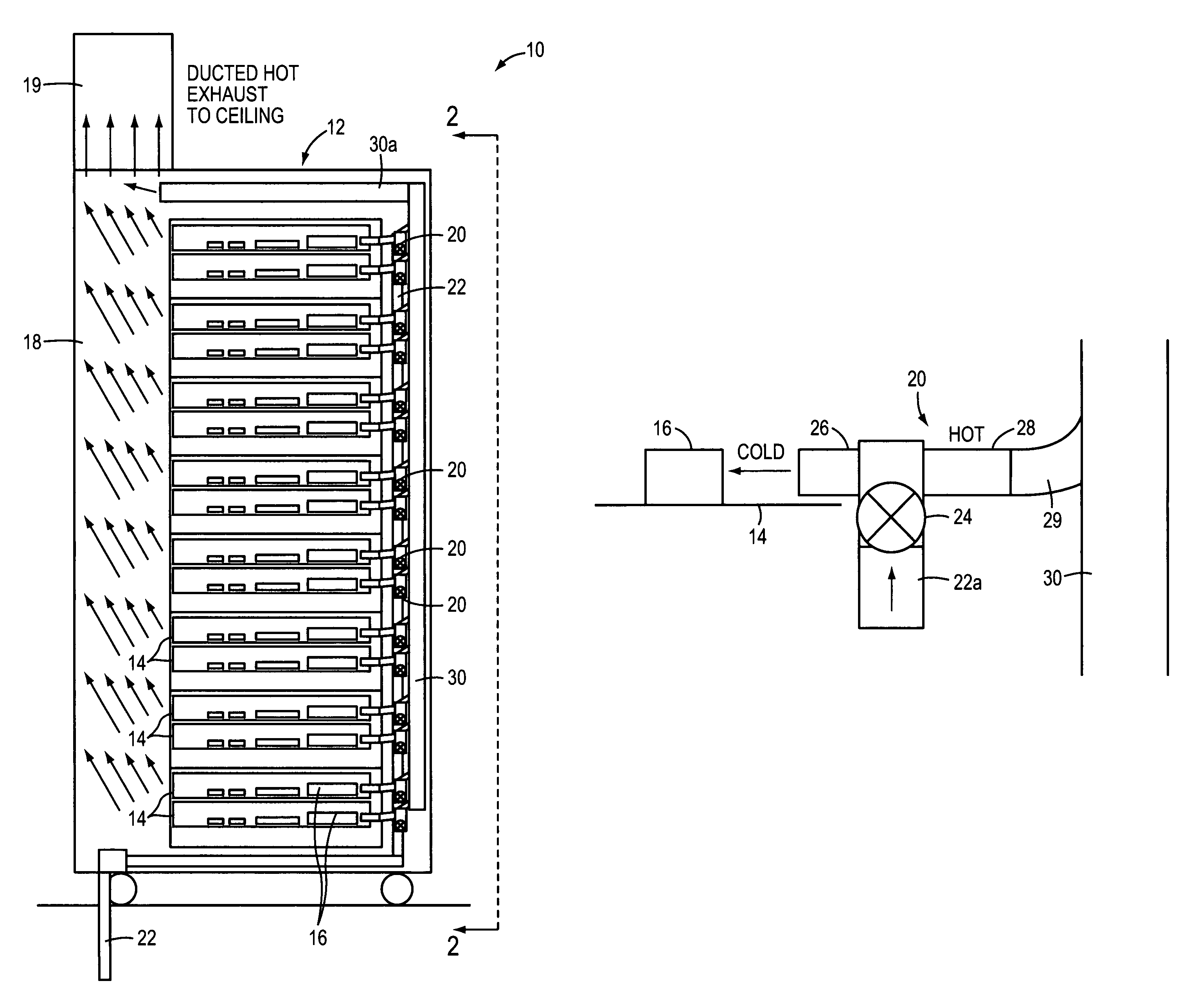
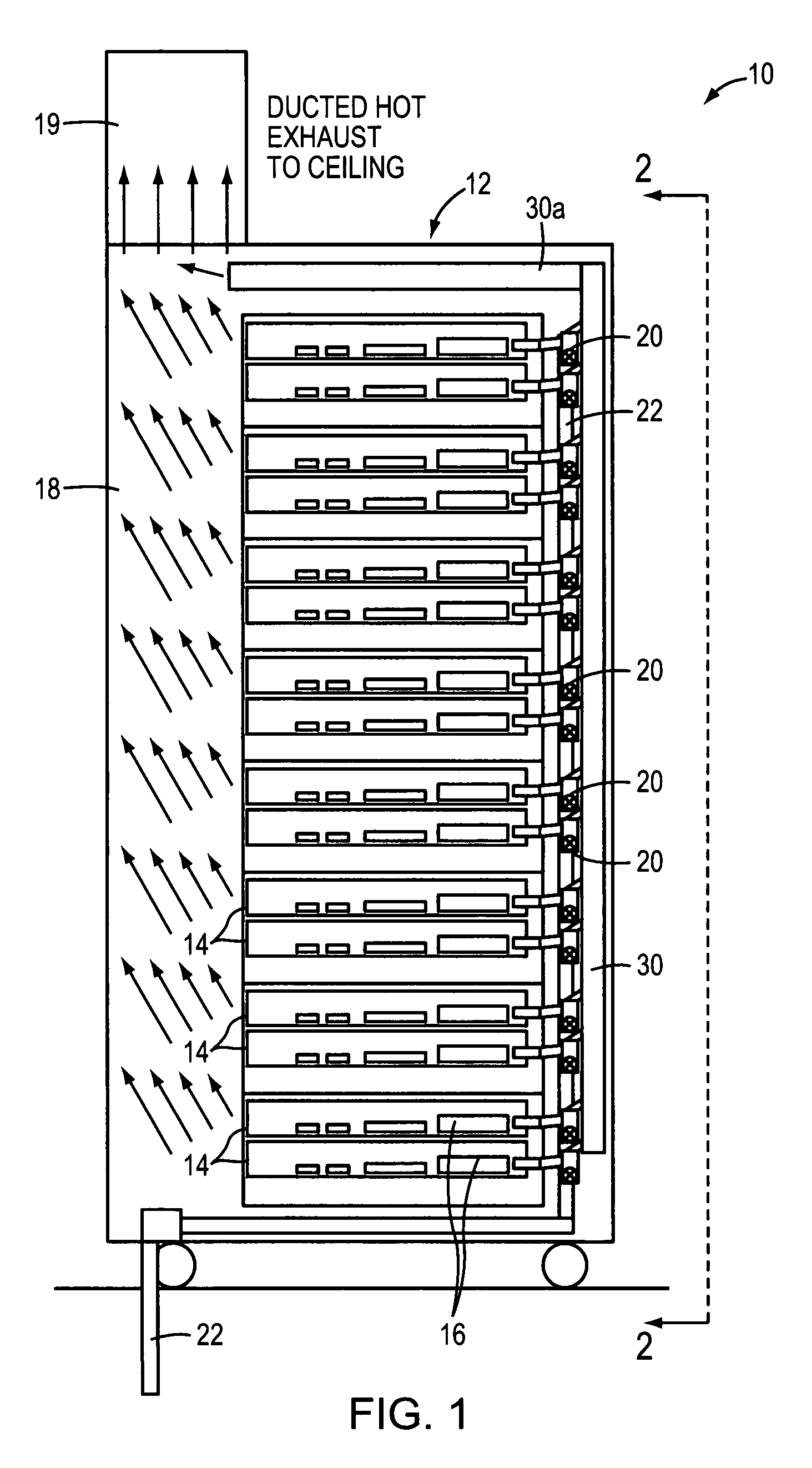
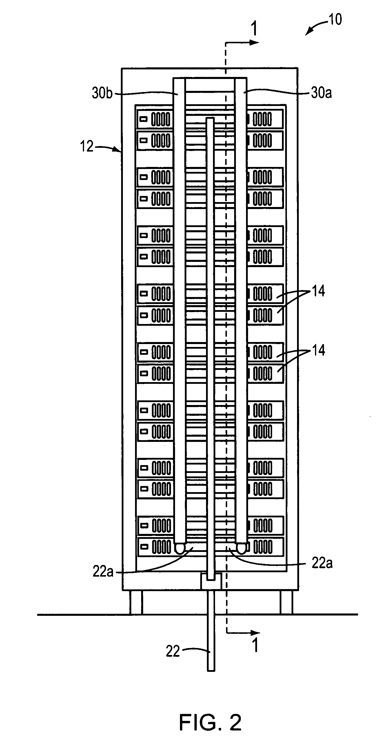
[0013]FIG. 1 is a diagram of a cross-sectional view, taken along line 1-1 of FIG. 2, of a cooling system for a data storage system 10 and FIG. 2 is a diagram of a front view, as seen from line 2-2 of FIG. 1, of the cooling system for the data storage system 10. Data storage system 10 includes a cabinet 12 housing a plurality of storage processor modules 14. Storage processor modules 14 include a number of components for processing data read and write commands between a host computer and data storage devices (not shown), including central processing units (“CPU”). In one embodiment, each module 14 includes two CPUs. Since FIG. 1 is a cross-sectional view of the system 10, only one CPU 16 of each module 14 can be seen. Cabinet 12 includes a chimney section 18 through which heat generated by the components is directed out of the cabinet through a duct 19.

[0014]The cooling system utilizes a plurality of vortex tube devices 20, each for directing cold air at the heat-generating component...


PUM


Abstract

A cooling method and system is disclosed which utilizes vortex tubes to generate and direct cold air over heat-generating components of an electronic system.

Description

FIELD OF THE INVENTION[0001]This invention relates generally to a method and system for providing cooling of electrical components and, more particularly, to a method and system for using vortex tubes to generate and direct cool air over heat-generating components of the data storage system.BACKGROUND OF THE INVENTION[0002]Critical to the proper operation of electronic systems is temperature control. The electronic components in these systems can generate much heat, which, unless quickly dissipated, can negatively affect the operational characteristics of those and other components and lead to system failure. As is known in the art, air is typically used to cool electronic components stored within system cabinets. One technique for such cooling is to mount a fan in an aperture in the top of such cabinets. Such a fan creates an air flow through the cabinet, cooling the housed electrical components.[0003]However, since fans can only move ambient air over the electronic components, the...

Claims


Application Information

Patent Timeline
Patent Type & Authority Patents(United States)
IPC IPC(8): H05K7/20
CPCH05K7/20736
Inventor FRENCH, F. WILLIAMGILDEN, SHELDON JOELNIGRO, JR., ARTHUR R.
Owner EMC CORP
Why Eureka
Try Eureka