Electric-motor-equipped vehicle

a technology of electric motors and motors, applied in the direction of motor/generator/converter stoppers, magnetic bodies, electric devices, etc., can solve the problems of unfavorable situation, difficult to appropriately control the phase difference between the first and second rotors only by centrifugal force, and inability to properly control the phase difference between the first and second rotors. , to achieve the effect of suppressing the generation of braking action, relatively increasing the driving efficiency, suppress

Inactive Publication Date: 2010-07-13
HONDA MOTOR CO LTD
View PDF13 Cites 5 Cited by
  • Summary
  • Abstract
  • Description
  • Claims
  • Application Information

AI Technical Summary

Benefits of technology

[0007]The present invention has been achieved in view of the above circumstances, and has an object to provide an electric-motor-equipped vehicle which easily and appropriately makes an induced voltage constant variable while suppressing complex constructions of the electric motor and the electric-motor-equipped vehicle, to thereby make it possible to extend an operational range of the rotation rate and an operational range of torque for improvement of operation efficiency, and also to extend a high-efficient operational range.

Problems solved by technology

Therefore, there arises a problem that it is impossible to control the phase difference at an appropriate timing including a halt state of the electric motor.
Furthermore, when the electric motor is likely to be subjected to vibrations from the outside, such as when the electric motor is mounted in a vehicle as a driving source, there arises a problem that it is difficult to appropriately control the phase difference between the first and second rotors only by the action of centrifugal force.
Therefore, there is a possibility that an unfavorable situation is brought about in which the relationship of the supply voltage and the counter electromotive voltage is reversed.
Therefore, there arises a problem that the control processing of the electric motor becomes complicated.

Method used


Image

  • Electric-motor-equipped vehicle
  • Electric-motor-equipped vehicle
  • Electric-motor-equipped vehicle

Examples


Embodiment Construction

[0092]Hereunder is a description of one embodiment of an electric-motor-equipped vehicle according to the present invention, with reference to the appended drawings.

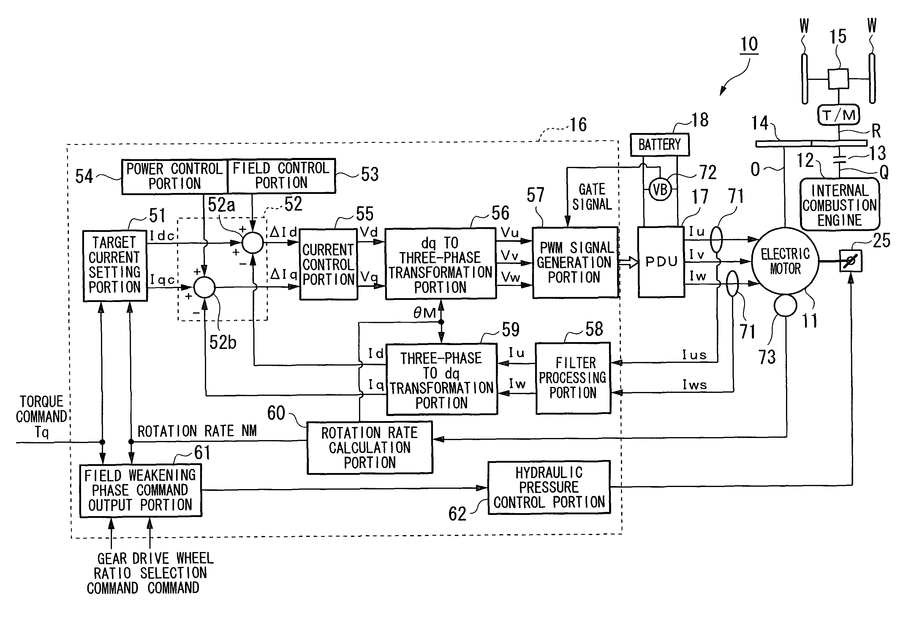
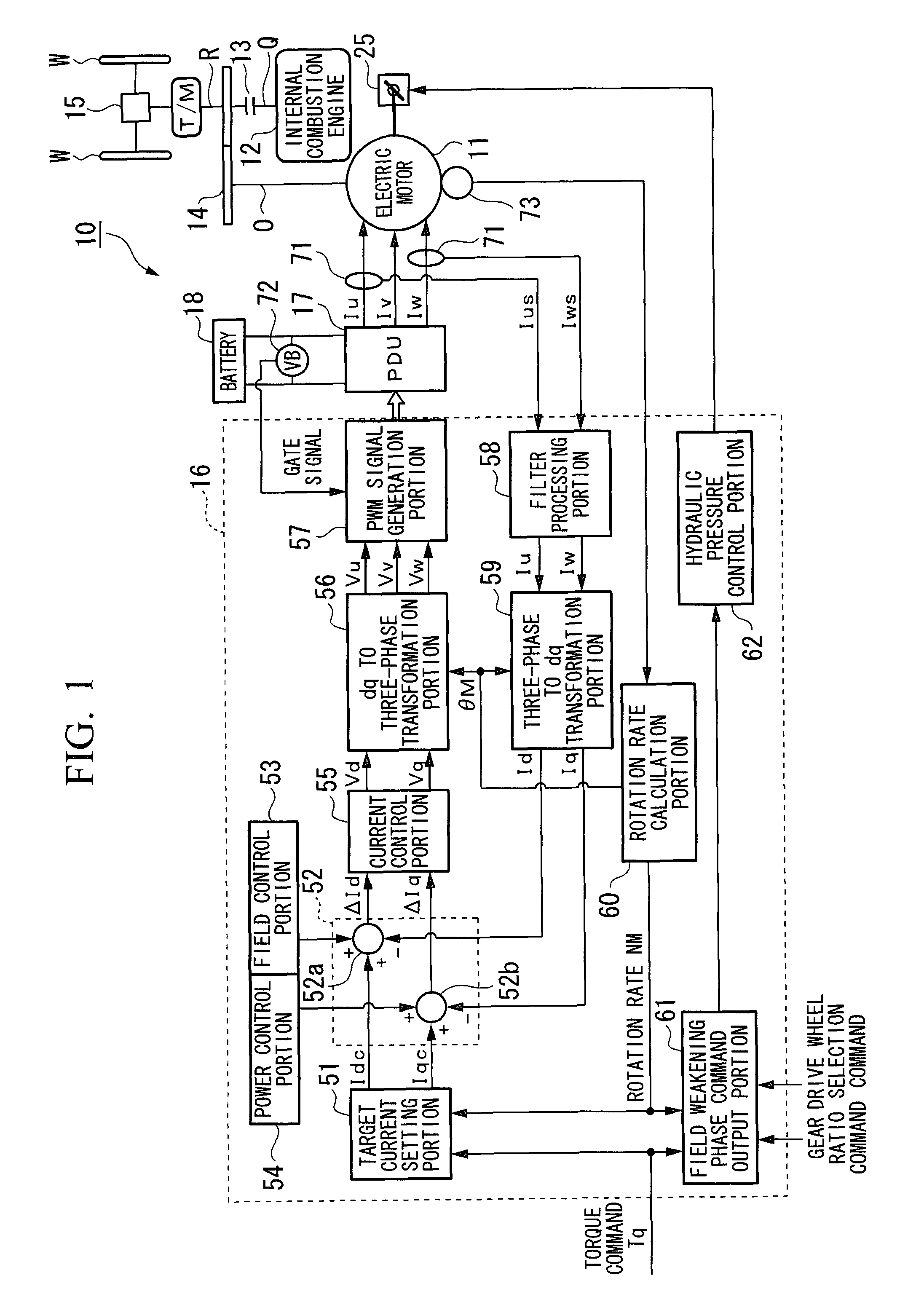
[0093]An electric-motor-equipped vehicle 10 (hereunder, referred simply as a vehicle 10) according to the embodiment is a hybrid vehicle provided with an electric motor 11 and an internal combustion engine 12 as driving sources, for example as shown in FIG. 1. Driving force(s) of at least either one of the electric motor 11 and the internal combustion engine 12 is (are) transmitted to drive wheels W via a transmission T / M.

[0094]In the vehicle 10, a rotation axis O of the electric motor 11 and an input axis R of the transmission T / M, which is connected to a crank axis Q of the internal combustion engine 12 via a clutch 13, are connected to each other via a motive force transmission mechanism 14, which transmits a motive force by means of, for example, a pair of engaging gears, a chain looped around gears which are integra...


PUM


Abstract

An electric-motor-equipped vehicle of the present invention includes an electric motor which receives a power supply from a storage apparatus and drives the vehicle, or assists a driving of the vehicle by an internal combustion engine. The electric motor includes: an inner circumference side rotor and an outer circumference side rotor which are each provided with magnet pieces, and rotation axes of which are coaxially arranged; a stator which is arranged on an outer circumferential side or an inner circumferential side of the inner circumference side rotor and the outer circumference side rotor; and a phase modification device capable of modifying a relative phase between the inner circumference side rotor and the outer circumference side rotor.

Description

TECHNICAL FIELD[0001]The present invention relates to an electric-motor-equipped vehicle.[0002]Priority is claimed on Japanese Patent Application No. 2006-052045, filed on Feb. 28, 2006, the contents of which are incorporated herein by reference.BACKGROUND ART[0003]Conventionally, there is known an electric motor having first and second rotors which are coaxially provided around the rotation axis of the electric motor, in which the relative position, that is, the phase difference between the first and second rotors is controlled according to the rotational speed of the electric motor or to the speed of the rotational magnetic field generated in the stator (for example, see Patent Document 1).[0004]In the electric motor, when the phase difference is controlled according to, for example, the rotational speed of the electric motor, the relative position in the circumferential direction between the first and second rotors is modified via a member which is displaced in the radial directi...

Claims


Application Information

Patent Timeline
Patent Type & Authority Patents(United States)
IPC IPC(8): H02K23/00B60L50/16
CPCB60K6/26B60K6/442B60K6/445B60K6/448B60K6/46B60K6/48B60K6/485B60K6/52B60L3/0046B60L11/123B60L11/14B60L15/025H02K1/276H02K7/12H02K16/02H02K21/24H02P21/005B60K1/02B60L2210/40B60L2220/14B60L2240/429B60L2270/20Y02T10/6217Y02T10/6221Y02T10/6226Y02T10/6234Y02T10/6243Y02T10/6265Y02T10/641Y02T10/643Y02T10/7005Y02T10/7077Y02T10/7241Y02T10/6239H02P21/00H02P21/30B60L50/61B60L50/16B60L58/15Y02T10/62Y02T10/64Y02T10/72Y02T10/7072Y02T10/70B60W2050/0052
Inventor ATARASHI, HIROFUMIISEGAWA, HIROYUKISATO, HIROMITSUKAIZUKA, MASAAKIABE, SHOEI
Owner HONDA MOTOR CO LTD
Why Eureka
Try Eureka