
Device for protection against voltage surges with parallel simultaneously triggered spark-gaps

a technology of voltage surge and protection device, which is applied in the direction of overvoltage protection resistor, emergency protective arrangement for limiting excess voltage/current, and arrangement responsive to excess voltage, etc., can solve the problems of limited capacity for carrying lightning current, limited capacity for breaking follow current, and voltage generated across

Inactive Publication Date: 2010-07-13
ABB FRANCE SAS
View PDF9 Cites 14 Cited by
  • Summary
  • Abstract
  • Description
  • Claims
  • Application Information

AI Technical Summary

Benefits of technology

[0020]The present invention seeks to remedy the various drawbacks listed above and proposes a novel surge protector device presenting characteristics that are improved from the point of view of its capacity for carrying lightning current and also its capacity for breaking follow current.
[0021]Another feature of the invention is to provide a novel surge protector device a very good level of protection.
[0022]Another feature of the invention is to provide a novel surge protector device of design that is particularly simple.

Problems solved by technology

Although such single spark gap devices are advantageous because of their design which is particularly simple, they nevertheless present certain drawbacks, associated in particular with their limited capacity for carrying lightning current and also their limited capacity for breaking follow current.
Firstly, when the current flowing through the first spark gap is below a predetermined value, the voltage generated across the terminals of the inductor coil is not sufficient to strike an arc in the second spark gap. Under such circumstances, current is not distributed between the two spark gaps, and as a result the capacity of the device for carrying lightning current corresponds substantially to the capacity for carrying lightning current provided by the first spark gap on its own.
Conversely, when the magnitude of the current flowing through the first spark gap is high, the voltage across the terminals of the inductor coil becomes large and is added to the voltage across the terminals of the spark gap, thereby degrading the quality of the peak-limiting performed by the spark gap and thus degrading the level of protection it provides.

Method used


Image

  • Device for protection against voltage surges with parallel simultaneously triggered spark-gaps
  • Device for protection against voltage surges with parallel simultaneously triggered spark-gaps
  • Device for protection against voltage surges with parallel simultaneously triggered spark-gaps

Examples


Embodiment Construction

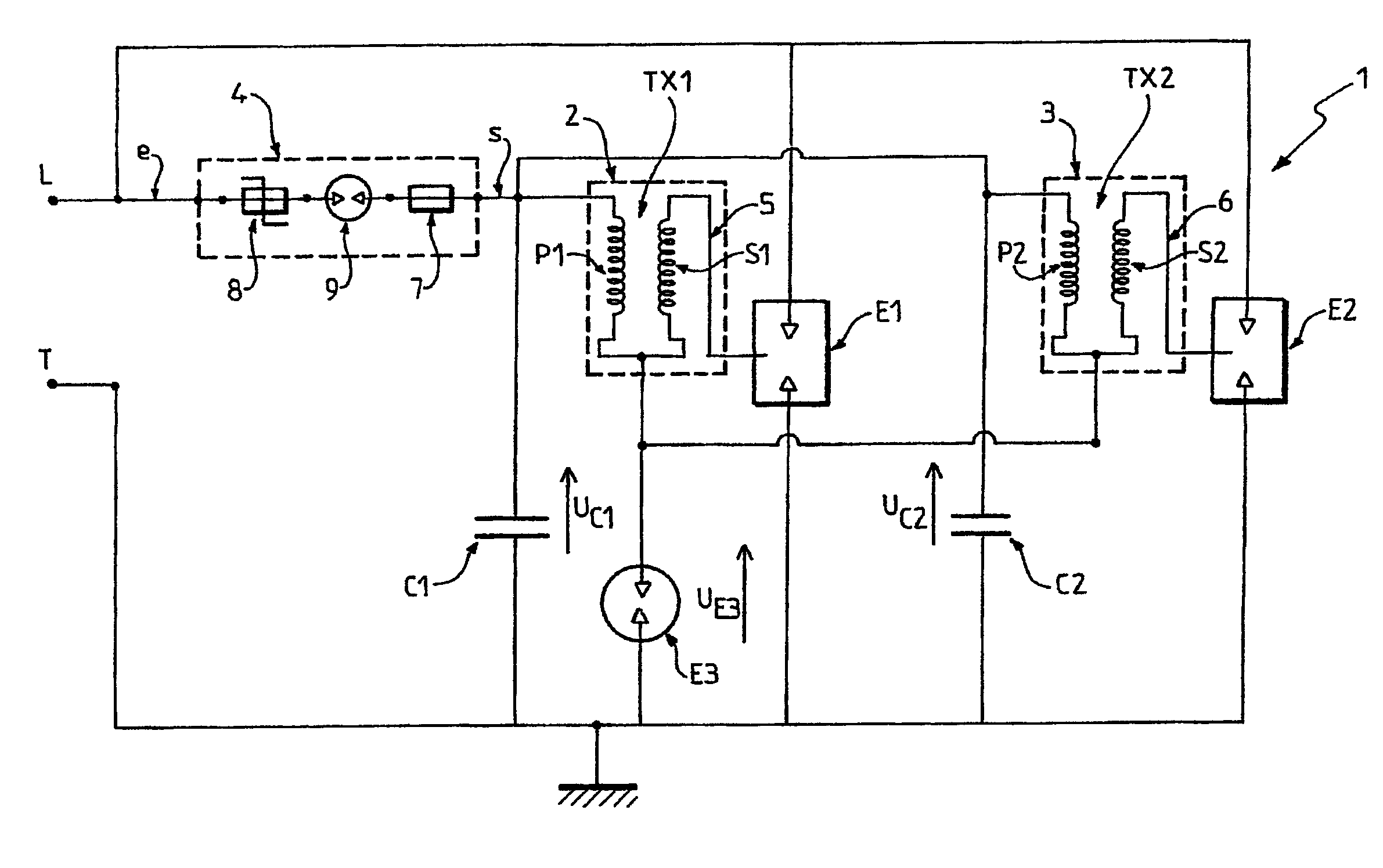
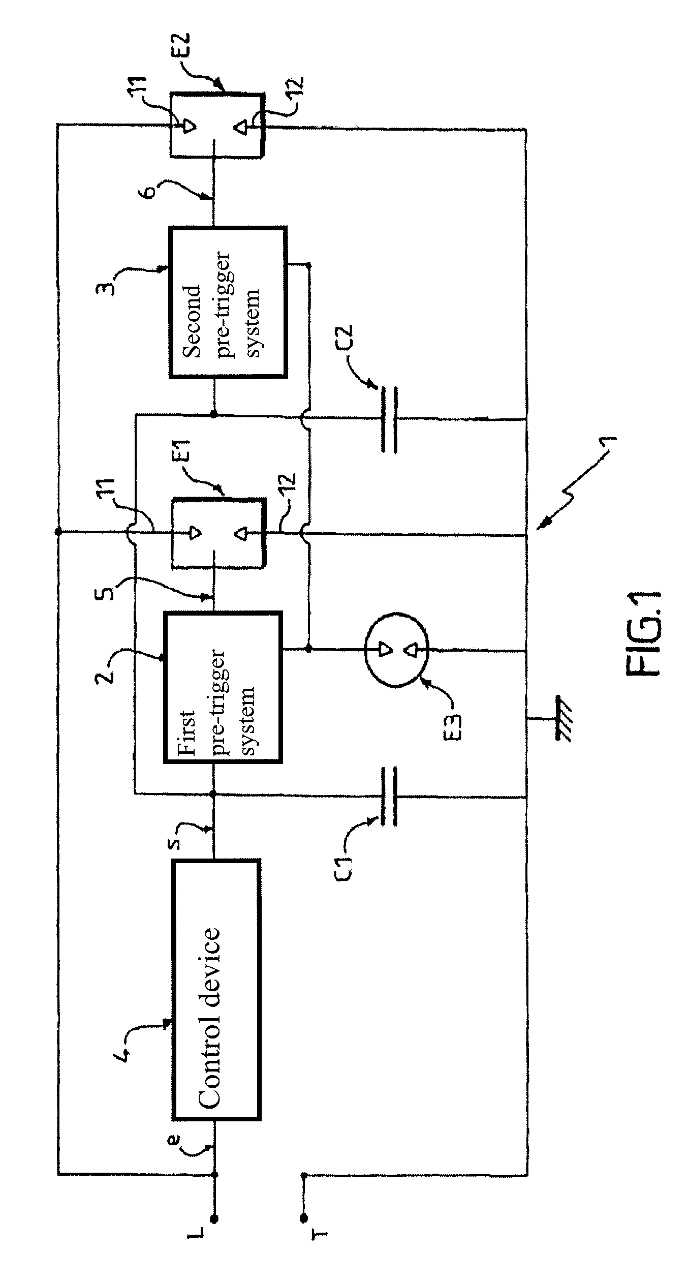
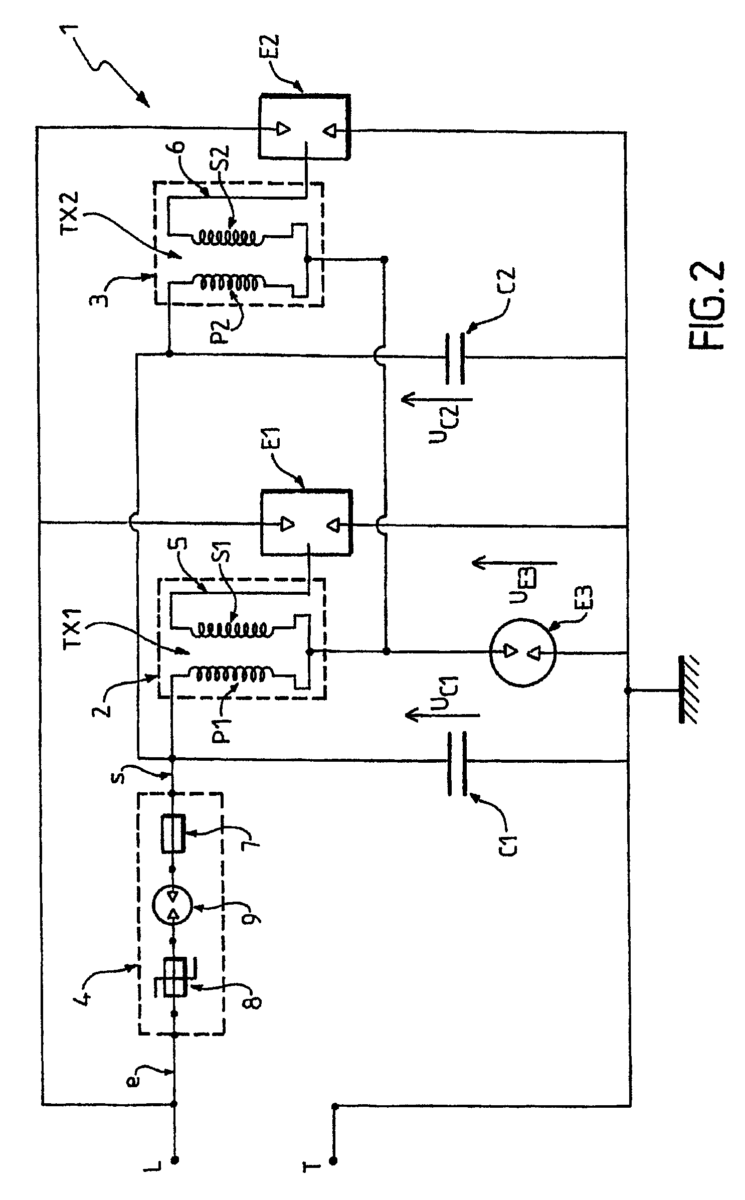
[0034]The surge protector device 1 in accordance with the invention is for connection in parallel with the electrical equipment or installation to be protected.

[0035]The term “electrical installation” refers to any type of apparatus or network that might be subjected to voltage disturbances, in particular to transient surges due to lightning.

[0036]The device is described with reference to FIGS. 1 and 2.

[0037]The surge protector device 1 is advantageously for connection between a phase L of the installation to be protected and ground T.

[0038]However, without going beyond the ambit of the invention, it is also possible to envisage that instead of being connected in parallel between a phase L and ground T, the device could be connected between neutral and ground, between the phase L and neutral, or indeed between two phases (for differential protection). Under all circumstances, the protector device 1 in accordance with the invention advantageously constitutes a single-pole protector d...


PUM


Abstract

A device for protection against voltage surges, comprising: a first spark gap (E1); a first pre-triggering system (2), electrically connected to the first spark gap (E1), so as to enable its being primed; a control device (4) electrically connected to the first pre-triggering system (2) so as to activate same. The invention is characterized in that it comprises at least a second spark gap (E2) mounted parallel to the first spark gap (E1), and electrically connected to a second pre-triggering system (3), such that the control device simultaneously activates the first and the second pre-triggering systems (2, 3), so as to trigger simultaneously the first and second spark gaps (E1, E2). The invention also concerns devices against voltage surges.

Description

PRIORITY CLAIM[0001]This patent application is the U.S. National Phase of International Application No. PCT / FR2004 / 003345, having an International Filing Date of Dec. 22, 2004, which claims priority to France Patent Application No. 0315551, filed Dec. 30, 2003, the disclosures of which are incorporated herein by reference in their entirety.FIELD OF THE INVENTION[0002]The present invention relates to the general technical field of devices for protecting electrical installations against voltage surges, in particular transient surges due to lightning.[0003]More particularly, the invention relates to a surge protector device of the spark gap lightning arrestor kind, the device comprising:[0004]a. a first spark gap;[0005]b. a first pre-trigger system electrically connected to the first spark gap in such a manner as to enable an arc to be struck therein; and[0006]c. a control device electrically connected to the first pre-trigger system in such a manner as to activate it.BACKGROUND OF THE...

Claims


Application Information

Patent Timeline
Patent Type & Authority Patents(United States)
IPC IPC(8): H02H3/20H01T2/02H02H9/06
CPCH02H9/06H01T2/02
Inventor CREVENAT, VINCENT ANDRE LUCIENGAUTIER, BORIS
Owner ABB FRANCE SAS
Learn More