
Design optimization system and method

a design optimization and optimization system technology, applied in the field of design optimization, can solve the problems of inability to identify the best design, difficult or computationally expensive calculation of these derivatives, and inability to achieve the convergence characteristics of many classes of problems, and achieve the effect of less time and higher performance and robustness

Active Publication Date: 2010-07-13
BOARD OF TRUSTEES OPERATING MICHIGAN STATE UNIV
View PDF5 Cites 12 Cited by
  • Summary
  • Abstract
  • Description
  • Claims
  • Application Information

AI Technical Summary

Benefits of technology

[0010]The present invention is advantageous over previous design optimization systems and methods in that potentially thousands of design iterations can be performed at the subsystem level in about the same amount of time required to perform 5-15 system level evaluations. Therefore, potentially hundreds or thousands of design parameters can be considered simultaneously. With this approach, engineers can achieve designs with significantly higher performance and robustness, and in less time. Furthermore, engineers can thoroughly explore new design concepts that were previously ignored due to their computational complexity.

Problems solved by technology

But mathematical methods used for optimization may not always identify the best design, and in these cases we seek to find as good a design as possible, or at least a design that is better than the existing one.
We are concerned here with relatively large optimization problems, where large may refer to the number of design variables and / or the CPU time required to evaluate the objective function for a particular design candidate.
Most such iterative approaches depend upon the calculation of sensitivity derivatives of the optima of each subsystem with respect to changes in the global variables, z. Often, the calculation of these derivatives is either very difficult or computationally very expensive.
This technique, however, has less than desirable convergence characteristics when applied to many classes of problems.
Namely, problems in which significant changes in the interaction variables occur during the iteration process may not converge to a near optimal solution, and may fail to converge at all.

Method used


Image

  • Design optimization system and method
  • Design optimization system and method
  • Design optimization system and method

Examples


Embodiment Construction

[0017]The following description of the preferred embodiment(s) is merely exemplary in nature and is in no way intended to limit the invention, its application, or uses.

[0018]We will first consider a particular special case of the broad problem class of interest for the purpose of describing the fundamental aspects of the new approach. In a subsequent section this approach will be generalized in several meaningful ways.

[0019]In large complex engineered systems (including structural, fluidic, thermal, acoustic, electro-magnetic, etc.), often only a subsystem or a small part of the system design needs to be modified to adapt or improve performance in some way. For example, to improve frontal crash safety in an automobile, an engineer might focus design changes on only the vehicle lower compartment rails and the bumper. To modify the lift or drag characteristics of an airplane, an aerospace engineer might focus only on the leading or trailing edge of a wing.

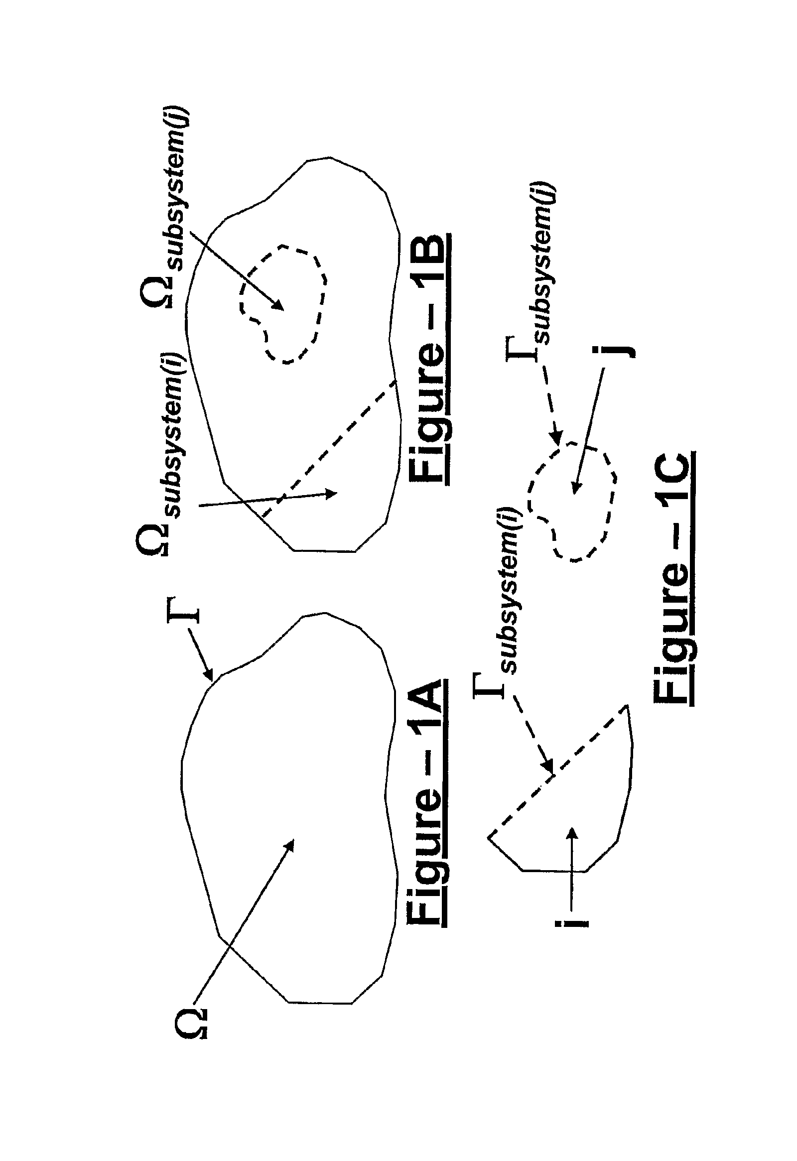
[0020]Referring to FIG. 1A, c...


PUM


Abstract

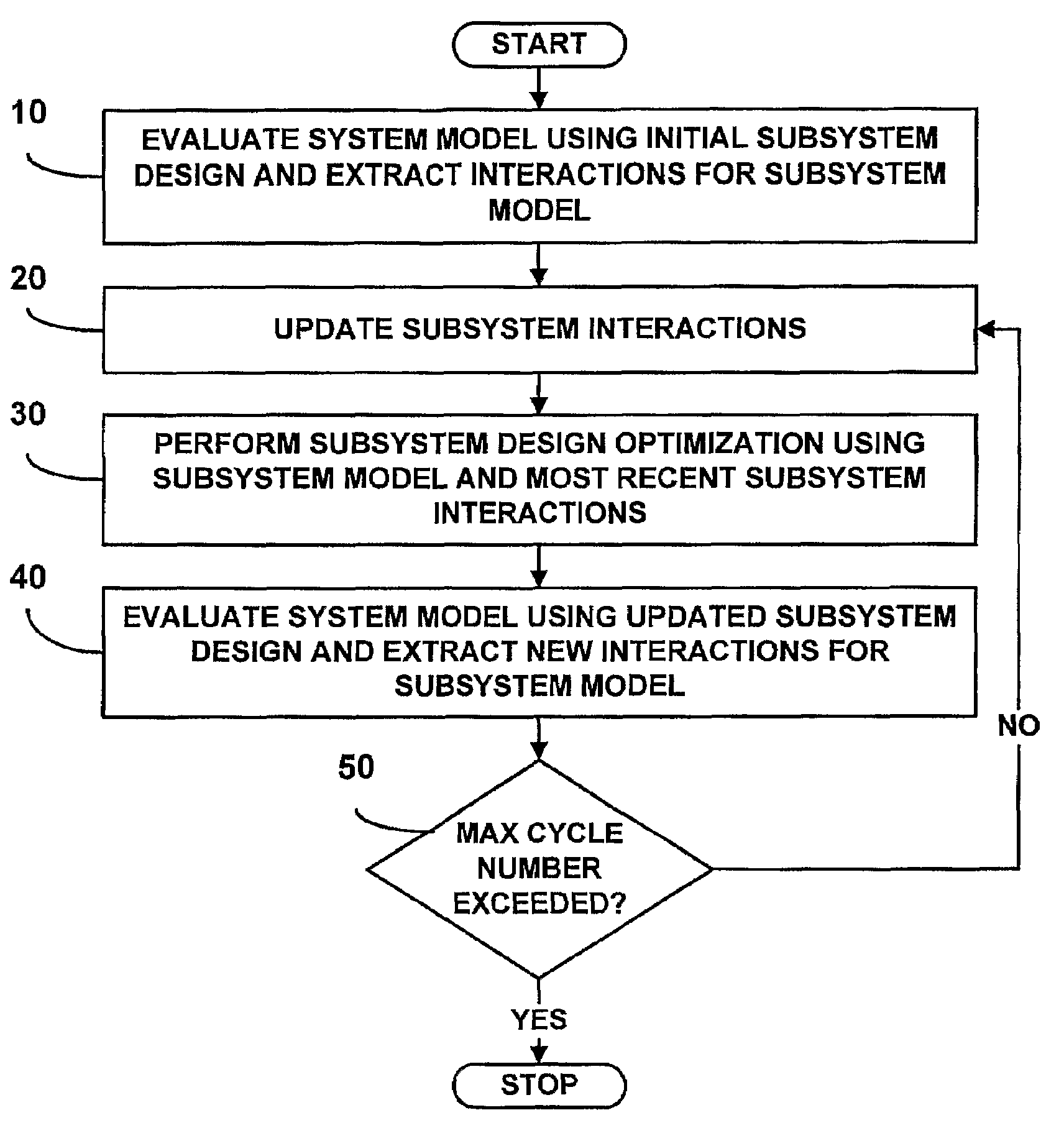
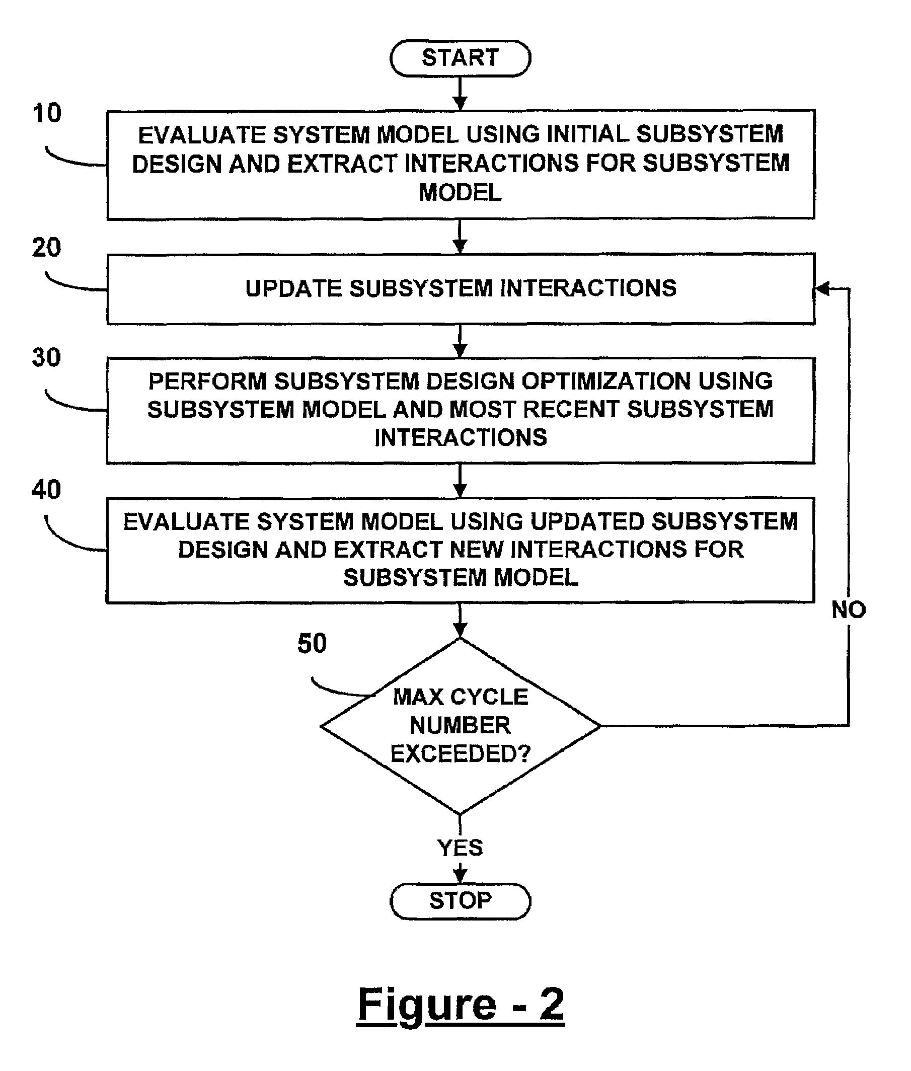
A design optimization system includes an initial design evaluation module evaluating a system model using initial subsystem designs to extract interactions between subsystem models and / or between the system and the subsystem models. An updating module updates the interactions for the subsystem models, and an optimization module performs subsystem design optimization using the subsystem model and most recently updated interactions, thereby obtaining an updated subsystem design.

Description

CROSS-REFERENCE TO RELATED APPLICATIONS[0001]This application claims the benefit of U.S. Provisional Application No. 60 / 569,595, filed on May 10, 2004. The disclosure of the above application is incorporated herein by reference in its entirety for any purpose.FIELD OF THE INVENTION[0002]The present invention generally relates to design optimization, and relates in particular to the solution of optimization problems that are decomposed to facilitate a multi-level solution process that utilizes selective update of interactions between subsystems and / or between the system and its subsystem(s) in a form that is controlled by weight functions whose spatial and temporal distributions are predetermined and whose magnitudes are varied stochastically within a selected range.BACKGROUND OF THE INVENTION[0003]Optimization is a process that seeks to identify the best design according to a specified measure, or objective function, while also satisfying certain restrictions, or constraints. But ma...

Claims


Application Information

Patent Timeline
Patent Type & Authority Patents(United States)
IPC IPC(8): G06F7/60G06F17/50G06F17/10G06F9/44G06F9/455
CPCG06F8/20G06F17/50G06Q10/04G06F2217/08G06F2217/10Y02T10/82G06F2111/06G06F2111/08G06F30/00
Inventor AVERILL, RONALD C.SIDHU, RAN MOHAN JIT SINGHHALEPATALI, PRAVEEN
Owner BOARD OF TRUSTEES OPERATING MICHIGAN STATE UNIV
Learn More