Combination motor casing and spear

a technology of motor casing and spear, which is applied in the direction of drilling machine and method, borehole/well accessories, underwater drilling, etc., can solve the problems of high cost, high risk, and high cost, and achieve the effect of avoiding damage, avoiding tool failure, and avoiding the use of tools

Active Publication Date: 2010-07-20
BAKER HUGHES INC
View PDF9 Cites 16 Cited by
  • Summary
  • Abstract
  • Description
  • Claims
  • Application Information

AI Technical Summary

Benefits of technology

[0005]A wellhead removal tool features a rotary cutter run by a Moyno type progressive cavity pump that is powered by fluid pumped through it. The stator of the motor has a gripping device with a series of collets or slip inserts that have grip features that face outwardly. A support shoulder on the grip assembly cooperates with a j-slot connection to the stator to allow a cone to be moved under the collets to push them into a grip position below or in a selected portion of the wellhead where the grip will not damage the wellhead internal components. Fluid pumped through the downhole motor causes the casing cutter blades to extend and rotate to cut the casing. The grip allows the wellhead to be lifted away from the casing for recovery. The grip can be retracted by use of the j-slot to allow the tool to be removed from the wellhead.

Problems solved by technology

Since the wellhead is a very expensive item, great care has to be taken to avoid damaging it in the cutting and removal process.
The problem with this design is that it is complex and expensive and the wellhead has to be configured to accept the external grapple hook-shaped members that have to be pivoted into position.
If the wellhead has no such grab locations, or if they are not in a specific location, the tool becomes useless in recovery of the wellhead.
The threaded connection to a subsea wellhead entails risk of damage to the wellhead at the threads or further internally.

Method used


Image

  • Combination motor casing and spear
  • Combination motor casing and spear
  • Combination motor casing and spear

Examples


Embodiment Construction

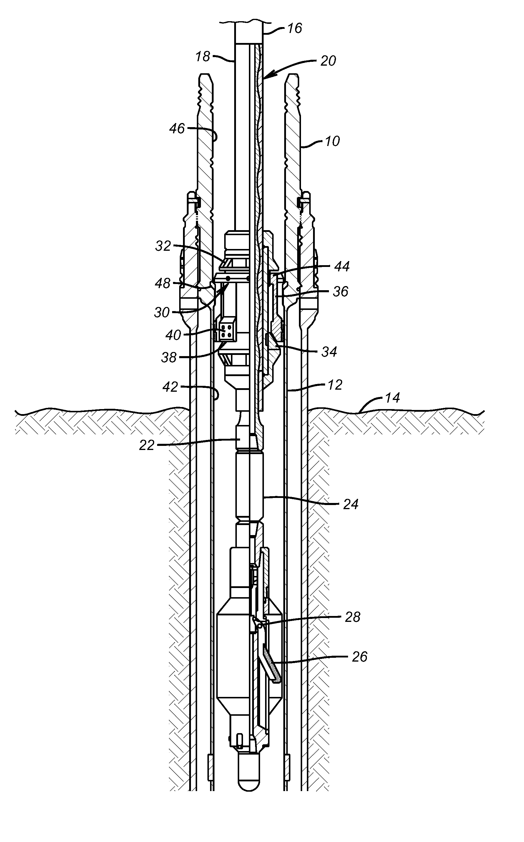
[0008]FIG. 1 illustrates a wellhead 10 to be removed from casing 12. The wellhead 10 is under water and typically close to the seabed 14. A string 16 is run from the water surface, not shown, to a stator 18 of a downhole motor 20. The motor 20 is preferably a Moyno type progressive cavity device that is operated with pumped fluid through the stator 18 that caused the rotor 22 to turn in response to pumped fluid through the stator 18. The pumped fluid passes out of the stator housing 18 and around the rotor 22 and enters the crossover 24. From there the pressure of the fluid that passes through the crossover 24 causes blades 26 to pivot about pivot 28 until contact with the casing 12 is made. Rotor 22 rotation runs the extended blades along the casing 12 until a complete cut of casing 12 is accomplished. When that happens, the flow to motor 20 is cut off and the decrease in pressure allows the blades 26 to retract about pivot 28. Those skilled in the art will appreciate that while a ...


PUM


Abstract

A wellhead removal tool features a rotary cutter run by a Moyno type progressive cavity pump that is powered by fluid pumped through it. The stator of the motor has a gripping device with a series of collets or slip inserts that have grip features that face outwardly. A support shoulder on the grip assembly cooperates with a j-slot connection to the stator to allow a cone to be moved under the collets to push them into a grip position below or in a selected portion of the wellhead where the grip will not damage the wellhead internal components. Fluid pumped through the downhole motor causes the casing cutter blades to extend and rotate to cut the casing.

Description

FIELD OF THE INVENTION[0001]The field of the invention is tools that allow wellheads to be separated from conductor pipe and casing string tubulars and recovered from the sea bed to surface when the well is to be abandoned.BACKGROUND OF THE INVENTION[0002]When a well is to be abandoned, the wellhead is normally cut from the supporting tubular string and used on other wells. Since the wellhead is a very expensive item, great care has to be taken to avoid damaging it in the cutting and removal process. It is also desirable in some cases to make the casing cut as close to the wellhead as possible.[0003]One example of how this was done in the past is illustrated in U.S. Pat. No. 5,318,115. The equipment illustrated there is a combination of a support and a motor driving a rotary tubing cutter with extendable blades. The support is an elaborate grapple design that features pivoting members that hook over the top of the wellhead and land in an external wellhead groove to brace the apparat...

Claims


Application Information

Patent Timeline
Patent Type & Authority Patents(United States)
IPC IPC(8): E21B29/00
CPCE21B29/005E21B31/16
Inventor MCKAY, GRAEME
Owner BAKER HUGHES INC
Why Eureka
Try Eureka