
Method for joining structural components

a structural component and structural technology, applied in the direction of auxillary welding devices, non-electric welding apparatus, auxillary devices, etc., can solve the problems of brittle phase, surface area, contamination of free non-overlapping surface areas, etc., and achieve the effect of improving the oscillation or vibration strength of the joining zon

Inactive Publication Date: 2010-07-20
MTU AERO ENGINES GMBH
View PDF10 Cites 3 Cited by
  • Summary
  • Abstract
  • Description
  • Claims
  • Application Information

AI Technical Summary

Benefits of technology

Ensures uniform heating, reduces mechanical stress, and enhances the vibration strength of the joining zone by preventing argon-filled pores, resulting in a stronger and more reliable joint.

Problems solved by technology

These temporarily free surface areas are exposed to a possible contamination, for example, if the linear friction welding is performed under the normal atmosphere, the free non-overlapping surface areas are exposed to contamination by oxygen whereby brittle phases can occur in the joining zone between the two structural components to be joined.
Such brittle phases impair the material strength of the junction or joint.
However, it has been found that even when the linear friction welding is performed in an argon atmosphere, contaminations or faults can occur in the junction or joining zone.
Such hose pores may have a negative effect on the so-called vibration or oscillation strength of the junction or joining zone produced by linear friction welding.

Method used


Image

  • Method for joining structural components
  • Method for joining structural components

Examples


Embodiment Construction

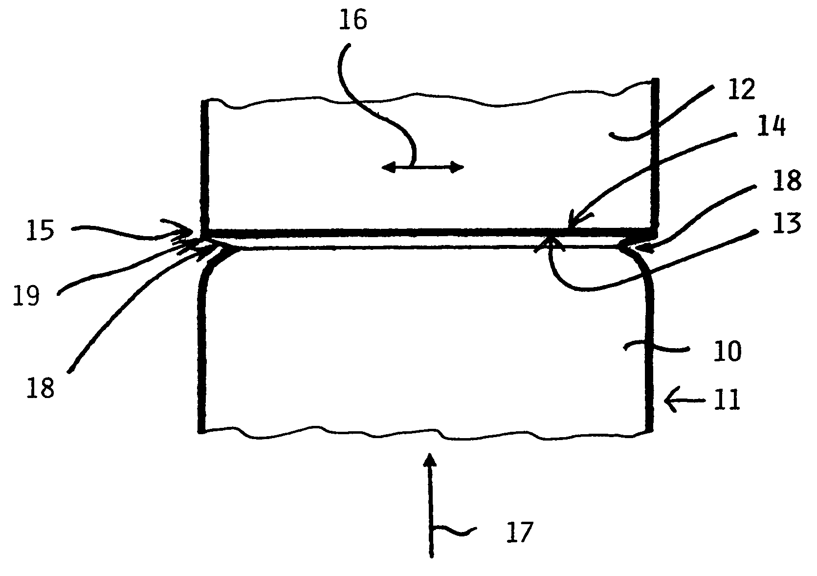
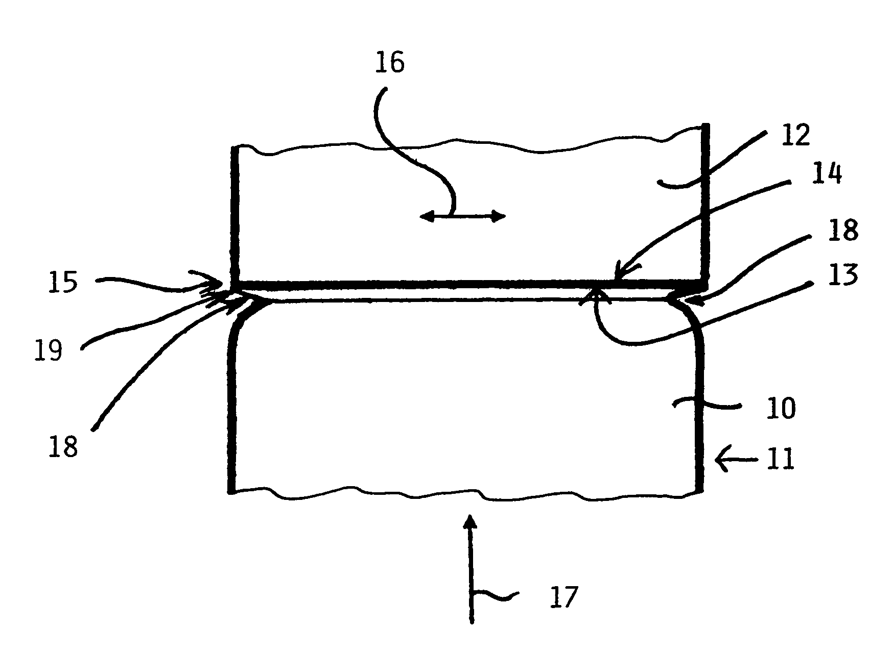
[0020]The single FIGURE illustrates the method according to the invention for joining structural components with reference to the example of producing or repairing an integral bladed gas turbine rotor. As shown, the radially inner end of a rotor blade 12 is to be joined to a radially outwardly facing blade hump 10 of a rotor base body 11. The joining of the rotor blade 12 to the rotor blade hump 10 of the rotor base body 11 is accomplished by an oscillating friction welding especially a linear friction welding. Prior to the welding step, each of the two structural components is provided with a respective joining surface 13 and 14 respectively. When the joining surfaces are joined, a joining zone 15 is formed between the two components. Once the two joining surfaces 13 and 14 are formed and aligned with each other by aligning the rotor blade 12 relative to the blade hump 10, the joining takes place conventionally by an oscillating friction welding such as linear friction welding wher...


PUM

PropertyMeasurementUnit
perimeteraaaaaaaaaa
elastically softaaaaaaaaaa
frictionaaaaaaaaaa

Abstract

Two structural components, such as a gas turbine rotor hub and a rotor blade, are integrally joined to each other by friction welding, particularly linear friction welding. For this purpose, each component is provided with a joining surface and at least one of the two components is provided with a groove next to the respective joining surface. The groove extends fully or partly around the respective joining surface and serves for reducing stress in a normal and radial direction of the respective joining surface, whereby a more uniform heating of the joining zone is achieved and joining faults are avoided or at least reduced during the friction welding.

Description

PRIORITY CLAIM[0001]This application is based on and claims the priority under 35 U.S.C. §119 of German Patent Application 10 2005 026 497.2, filed on Jun. 9, 2005, the entire disclosure of which is incorporated herein by reference.FIELD OF THE INVENTION[0002]The invention relates to a method for joining structural components, particularly joining a rotor blade or blades to a rotor base body or hub. This method is particularly suitable for the production of new gas turbine rotors and for the repair of gas turbine rotors having integral rotor blades.BACKGROUND INFORMATION[0003]Friction welding is commonly or widely used as a joining method. in a manufacture of gas turbines. Friction welding is a method within the group of so-called pressure welding methods. Friction welding permits joining or interconnecting structural components by friction. In connection with linear friction welding, one of the structural components is moved back and forth in a translatory direction whereas the oth...

Claims


Application Information

Patent Timeline
Patent Type & Authority Patents(United States)
IPC IPC(8): B23K20/12
CPCB23K20/1205B23K20/129B23P6/005F01D5/005F01D5/3061B23K2201/001F05B2230/239F05D2230/80B23K2101/001
Inventor BAMBERG, JOACHIM
Owner MTU AERO ENGINES GMBH
Learn More