Valve assembly

a valve and assembly technology, applied in the direction of instruments, catheters, process and machine control, etc., to achieve the effect of promoting health and enhancing li

Active Publication Date: 2010-07-20
ICU MEDICAL INC
View PDF252 Cites 97 Cited by
  • Summary
  • Abstract
  • Description
  • Claims
  • Application Information

AI Technical Summary

Benefits of technology

[0022]Preferably, the medical material is in solid, liquid or gaseous form or a combination thereof and has beneficial properties to enhance life, to promote health, to cure and / or treat a disease, condition or ailment, to monitor and / or indicate a bodily function or a combination thereof. For example, the medical material may be useful for, among others, IV therapy, implantation, stem cell therapy, oncology therapy, blood transfusion and / or organ transplantation.

Problems solved by technology

This is problematic since many medications and biological fluids are sensitive (or can degrade when exposed) to the environment.

Method used


Image

  • Valve assembly
  • Valve assembly
  • Valve assembly

Examples


Embodiment Construction

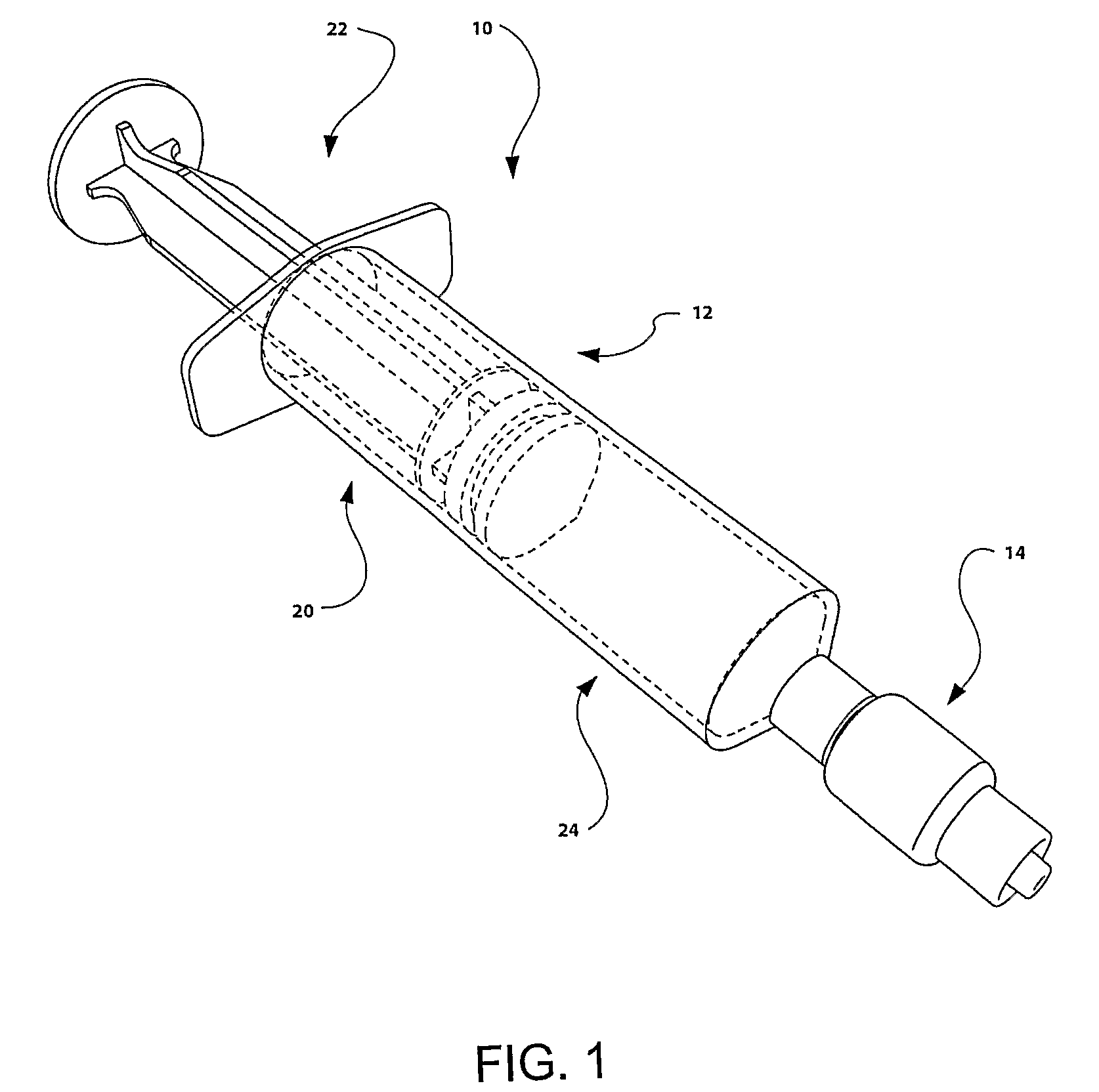
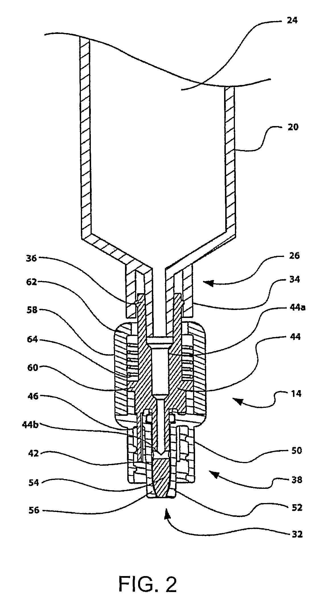
[0032]Referring to the figures, and in particular FIG. 1, there is provided a syringe assembly 10 comprising a syringe 12 and a valve unit 14. The syringe 12 has a chamber 20 containing a plunger 22 to form a cavity 24. Referring to FIG. 2, the cavity has an outlet 26 and the valve unit 14 is located downstream of the outlet 26 for coupling the cavity 24 with a medical accessory such as a needle 30 (as shown in FIGS. 3 and 4). The valve unit 14 has an outlet 32 and flow control means, as will be described, to control fluid flow through the outlet, the flow control means being operable to open the outlet when the coupling section is operatively connected with the medical accessory, the flow control means being operable to close the outlet when the valve unit is disconnected from the medical accessory and to remain closed until connected once again with a medical accessory.

[0033]In this case, the chamber 20 includes a first male luer end portion 34 adjacent the outlet 26 and the valve...


PUM


Abstract

Disclosed herein is a valve assembly comprising a male luer end portion and a female luer end portion and a passage for the transfer of fluids extending between the male and female luer end portions, valve means movable between a first position, in which the passage is closed, and a second position, in which the passage is open, biasing means for biasing the valve means toward the first position, and actuating means extending into the male luer end portion and coupled to the valve means to actuate the valve means when a female luer end portion of a medical accessory is engaged with the male luer end portion.

Description

[0001]This application is a national stage application filed under 35 U.S.C. 371 based on International Application No. PCT / US04 / 42723 filed Dec. 21, 2004 which claims benefit of U.S. Provisional Application No. 60 / 532,916 filed Dec. 30, 2003.BACKGROUND OF THE INVENTION[0002]1. Field of the Invention[0003]The present invention relates to medical fluid delivery valves and more particularly to valve assemblies for use with syringes or other medical dispensing devices.[0004]2. Description of the Related Art[0005]Syringes are commonly used to deliver medications and other biological fluids to a patient. The syringe typically has a plunger which is sealingly engaged with an outer cylindrical chamber to form an inner fluid—receiving chamber. A ‘male’ luer fitting is usually provided at a delivery end of the chamber which receives a female luer fitting with a needle assembly or the like. The fluid channel joining the cavity to the luer fitting is usually open, so that when the needle is re...

Claims


Application Information

Patent Timeline
Patent Type & Authority Patents(United States)
IPC IPC(8): A61M25/16A61M5/14A61M5/168A61M5/31A61M5/34A61M39/26F16L29/02
CPCA61M5/3134A61M39/26A61M5/31A61M39/10A61M39/22A61M5/14A61M5/16881A61M5/34A61M2205/19A61M2005/3128A61M2005/3103A61M2039/1033A61M2039/1066
Inventor SIMPSONGILLESPIE, WALTER D.MATSUURA, DAVID G.
Owner ICU MEDICAL INC
Why Eureka
Try Eureka