Medical device guidance from an anatomical reference

a medical device and anatomical reference technology, applied in the field of medical device deployment and use guidance, can solve the problems of increasing the complication, time and expense of a medical procedure, advanced to the point of regular clinical use or undefeated add cost, and large, bulky equipment and/or additional imaging set-up and use time to the overall procedure, so as to reduce the cost, reduce the time and cost, and ensure the effect of accuracy

Active Publication Date: 2010-07-20
BOSTON SCI SCIMED INC
View PDF13 Cites 0 Cited by
  • Summary
  • Abstract
  • Description
  • Claims
  • Application Information

AI Technical Summary

Benefits of technology

[0007]In one embodiment, there may be a guide catheter with a bend at its distal end such that its distal orifice is located at an angle with respect to the longitudinal axis of the catheter, through which a medical instrument, such as a percutaneous myocardial revascularization laser may be operated. This catheter is equipped with strain gauges along its wall, which measure localized stresses in the wall as the tube bends along a curved path. The stress indications provided by the strain gauges provide an indication of the bending of the catheter, for example, indicating which portion of the catheter is at the inside of the curve, and which portion is at the outside of the curve. If the strain gauges are located at a portion of the catheter which is bent as it passes through an anatomic reference geometry or region with a known configuration (an “anatomical reference”), such as through the aorta arch as the catheter passes though the aorta on the way to the left ventricle, the orientation of the distal catheter orifice may be simply and reliably determined. This information, combined with information obtained from fluoroscopic imaging from a single direction and knowledge of the orientation of the anatomical reference relative to the target site, permits a physician to efficiently and reliably determine whether the medical device is properly positioned and oriented with respect to the target site.
[0010]Because the present invention permits rapid, reliable determination of the position and orientation of medical devices with minimal imaging equipment and procedural complication, proper placement of minimally-invasive medical devices may be reliably achieved in less time and at a lower cost. These benefits may permit a reduced length of time the patient must be under anesthesia or subjected to radiation from fluoroscopy, thus increasing patient safety and lowering costs due to decreased demand for physician, supporting personnel and operating facility time for each procedure, and minimized capital equipment and operating costs due to decreased imaging equipment requirements.

Problems solved by technology

The need for multiple views of the device increases the complication, time and expense of a medical procedure, as either multiple fluoroscopes must be employed to obtain the desired views, or a single fluoroscope must be sequentially set up, used, repositioned, etc. to provide adequate imaging coverage.
Alternative imaging techniques that may provide higher resolution in the future have demonstrated some potential (such as MRI-based catheter imaging techniques); however, such developments have not as yet advanced to the point of regular clinical use or undesirably add cost, large, bulky equipment and / or additional imaging set-up and use time to the overall procedure.

Method used


Image

  • Medical device guidance from an anatomical reference
  • Medical device guidance from an anatomical reference
  • Medical device guidance from an anatomical reference

Examples


Embodiment Construction

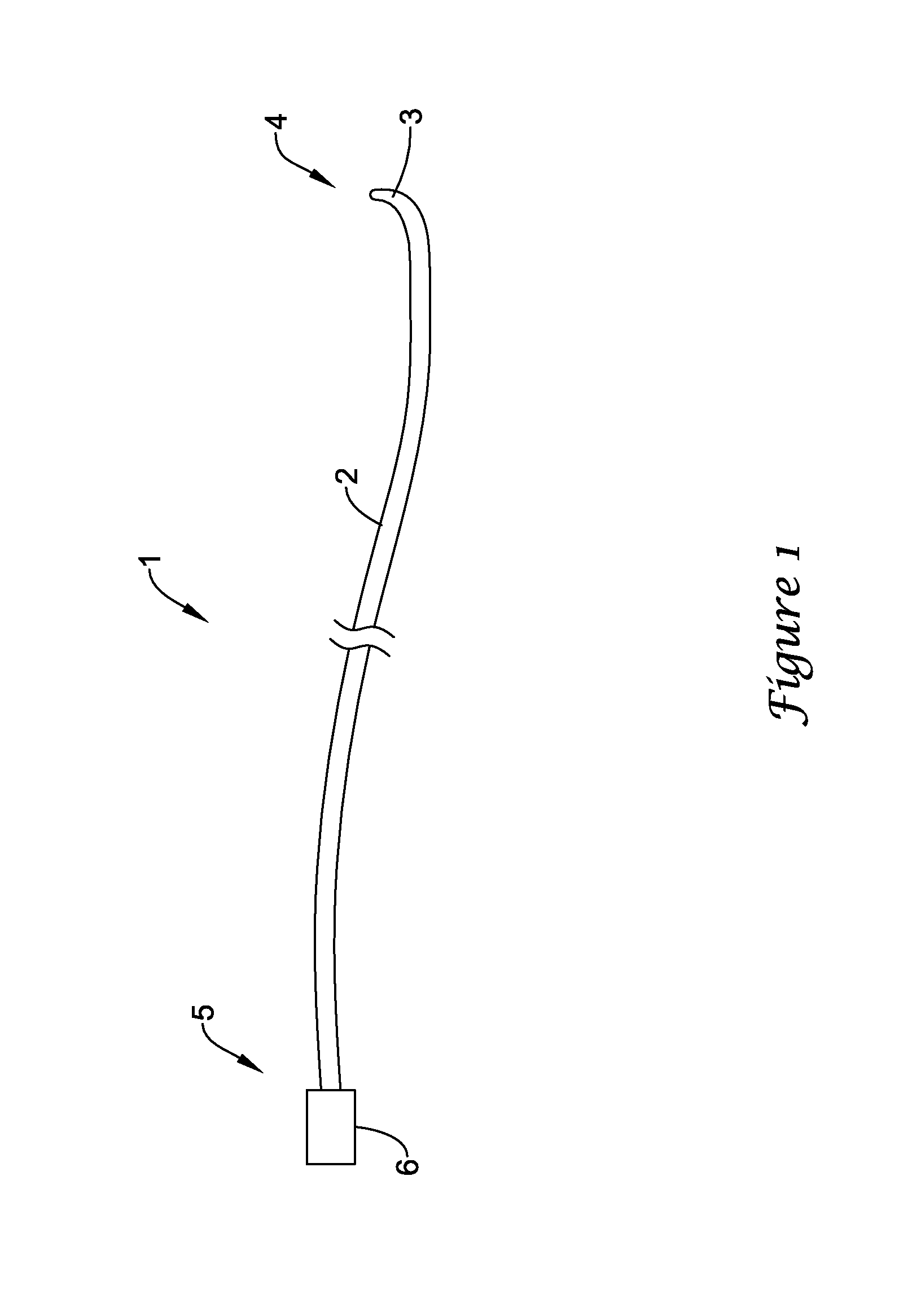
[0021]FIG. 1 illustrates a catheter 1 in accordance with an embodiment of the present invention. Catheter 1 comprises a tube 2 forming a lumen 8 therein (shown in FIG. 2), with a distal orifice 3 formed at a distal end 4 of catheter 1. At a proximal end 5 of catheter 1 are fittings for use of the catheter, illustrated schematically by terminal box 6, including, for example, means for guiding and manipulating the catheter toward a target site, provisions for passage of fluids and / or other medical devices through lumen 8 to a target site via distal orifice 3, and connections for reading instrumentation contained on or within catheter 1. Catheter 1 may be formed from materials and processes well known in the catheter manufacture art.

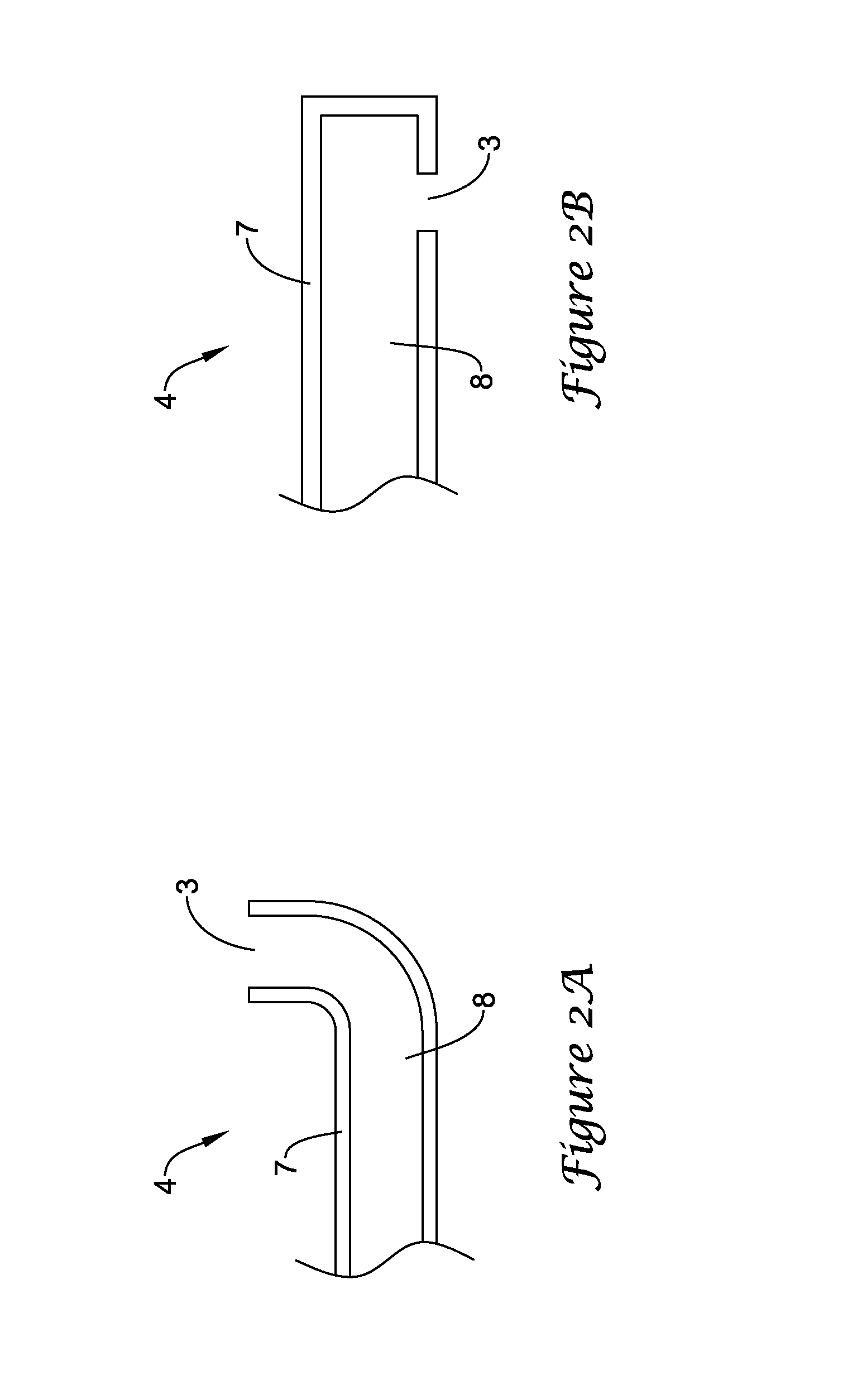
[0022]FIG. 2a illustrates the configuration of distal end 4 in the present embodiment. FIG. 2a is a longitudinal cross-section view of catheter 1 showing tube wall 7 and the lumen 8 formed therein. Catheter 1 may alternatively include multiple lumens; howev...


PUM


Abstract

A system and method for simply and reliably determining the location and orientation of a medical device within a patient's body. A medical device, such as a catheter, has bending indicators on or imbedded in its wall, and passes through an anatomical reference of known orientation relative to a target site within the patient. Information from the tube bending indicators permits determination of the orientation of a feature, such as an orifice, at the distal end of the medical device relative to the anatomical reference. From the known orientation of the anatomical reference, and information on the location and orientation of the distal end of the medical device obtained from fluoroscopic imaging from a single direction, the physician may reliably determine the orientation of the distal feature relative to the target site, eliminating the need for imaging from multiple directions.

Description

FIELD OF THE INVENTION[0001]The present invention is directed to the field of guidance for medical device deployment and use within the body of a patient.BACKGROUND[0002]Medical catheters, guide catheters and guide tubes are used for innumerable minimally-invasive medical procedures, wherein a tube is inserted into a lumen in a patient's body, such as a blood vessel, and maneuvered to a target site, such as a heart chamber or another blood vessel. These catheters and guide tubes may be used as conduits for a variety of medical procedures, including delivery of therapeutic drug doses to target tissues, delivery of medical devices such as lumen-reinforcing or drug-eluting stents, and guiding medical instruments to a target site to perform a surgical procedure, such as tissue rescission, ablation of obstructive deposits or myocardial revascularization.[0003]In order to accurately maneuver a catheter or similar medical device (such as a guide tube or a guide wire) through a body lumen t...

Claims


Application Information

Patent Timeline
Patent Type & Authority Patents(United States)
IPC IPC(8): A61F4/00A61B1/00A61B5/05A61M25/01
CPCA61B5/061A61M25/01A61M25/0105
Inventor FREYMAN, TOBYMICKLEY, TIMOTHY J.
Owner BOSTON SCI SCIMED INC
Why Eureka
Try Eureka